34
3-12
+
+
3
12
1
P1
2
P3
3.10 CONVERTING THE BOILER TO
OTHER TYPES OF GAS.
If the boiler has to be converted to a different gas
type to that specified on the data plate, request
the relative conversion kit for quick and easy
conversion.
The gas conversion operation must be carried
out by an authorised company (e.g. Immergas
After-Sales Technical Assistance Service).
To convert to another type of gas the following
operations are required:
- disconnect the appliance;
- Change the sleeve with Venturi (det. 4 fig.
1-25);
- change the gas nozzle (det. 3 fig. 1-25);
- re-power the appliance;
- regulate the maximum heat output by varying
the number of fan revs. (parameter P25 “Max
number of fan revs in CH mode”) according to
par. 3.24;
- regulate the minimum heat output by varying
the number of fan revs. (parameter P26 “Min
number of fan revs in CH mode”) according to
par. 3.24;
- activate the chimney sweep function;
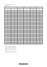
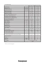
- check the CO
2
value on the table in par. 3.25,
especially:
- check the CO
2
value in the flue with chimney
sweep at 0%;
- check the CO
2
value in the flue with chimney
sweep at 100%;
- exit the chimney sweep function;
- seal the gas flow rate regulation devices (if
settings are modified);
- after completing the conversion, apply the
sticker, contained in the conversion kit, near
the data-plate. Using an indelible marker pen,
cancel the data relative to the old type of gas.
These adjustments must be made with reference
to the type of gas used.
3.11 CHECKS FOLLOWING
CONVERSION TO ANOTHER TYPE
OF GAS.
After making sure that transformation was
carried out with the Venturi and a nozzle of
suitable diameter for the type of gas used and
the calibration has been performed at the correct
num. of revs, check that:
- the burner flame is not too high and that it is
stable (does not detach from burner);
- there are no leaks from the gas circuit.
N.B.:
all boiler adjustment operations must
be carried out by a qualified technician (e.g.
Immergas After-Sales Assistance).
3.12 ADJUSTMENT OF THE AIR-GAS
RATIO.
Calibration of minimum CO
2
Turn the boiler on and start the chimney sweep
functions at minimum output (0%). To have an
exact value of CO
2
the technician must insert
the sampling probe to the bottom of the sample
point, then check that the CO
2
value is that
specified in the table in par. 3.25, on the con-
trary, regulate the screws (3 fig. 3-12) (Off-Set
regulator). To increase the CO
2
value, turn the
adjustment screw (3) in a clockwise direction and
vice versa to decrease it.
Calibration of maximum CO
2
.
When you finish the minimum CO
2
adjustment,
turn the boiler on and start the chimney sweep
function at the maximum output (100%). To have
an exact value of CO
2
the technician must insert
the sampling probe to the bottom of the sample
point, then check that the CO
2
value is that spec-
ified in the table in par. 3.25, otherwise, adjust
the screw (12 fig. 3-12) (gas flow rate regulator).
To increase the CO
2
value, turn the adjustment
screw (12) in an anti-clockwise direction and vice
versa to decrease it.
At every adjustment variation on the screw (12)
it is necessary to wait for the boiler to stabilise
itself at the value set (about 30 sec.).
3.13 CH OUTPUT ADJUSTMENT.
If it is necessary to change the CH output, you
will need to adjust the “P08” maximum CH out-
put and “P09” minimum CH output parameters.
To check the regulated heat output value, com-
pare the no. of fan revs with that in the table
(par. 3.24).
3.14 OUTPUT ADJUSTMENT DURING
DHW (ONLY IN COMBINATION
WITH AN OPTIONAL EXTERNAL
STORAGE TANK).
If it is necessary to change the DHW output,
you will need to adjust the “P20” maximum
DHW output and “P21” minimum DHW output
parameters.
To check the regulated heat output value, com-
pare the no. of fan revs with that in the table
(par. 3.24).
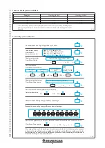
3.15 “CHIMNEY SWEEP” FUNCTION.
This function allows the technician to check
the combustion parameters. Boiler operation in
chimney sweep function can be adjusted to an
output between 0% and 100%.
To enable the function press and hold down “A”
If there is a common flow probe, it is possible to
activate the chimney sweep function by press-
ing buttons “A” and “B” simultaneously. In this
case, the plant pump is activated as well as the
boiler (in the “simple cascade” both boilers are
activated) The output is adjusted from the + and
- DHW adjustment buttons at a range between
0 and 100%, while using the + and - buttons for
CH adjustment, the percentage changes by 1%
each time they are pressed.
In this state all adjustments are excluded and
only the temperature safety thermostat and the
limit thermostat remain active. When the checks
are finished disable the function by pressing and
holding down button “A”.
If you enable the function, you will need to wait
approximately 30’’ to reach the set output (3’ on
the Slave boiler).
3-7
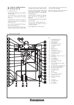
Key:
1 - Gas valve inlet pressure point
2 - Gas valve outlet pressure point
3 - Off/Set adjustment screw
12 - Outlet gas flow rate regulator
Gas Valve 848
Содержание VICTRIX PRO 35 2ErP
Страница 1: ...IE Instruction and warning book VICTRIX PRO 35 55 2 ErP 1 041662ENG...
Страница 2: ......
Страница 38: ...38 3 15 1 6 8 9 9 12 12 10 11 13 13 13 13 A A Rif A 7 7 Ref A...
Страница 49: ...49...
Страница 50: ...50...
Страница 51: ...51...


