26
2.8 BOILER SHUTDOWN.
Disconnect the main switch (1) taking it to the
“0” position and close the gas cock upstream
from the appliance.
Never leave the boiler switched on if left unused
for prolonged periods.
2.9 RESTORING CENTRAL HEATING
SYSTEM PRESSURE.
Periodically check the system water pressure.
The boiler manometer should indicate a value
not below 0.5 bar.
If the pressure is below 0.5 bar (with cold system)
the water inside the system must be restored.
N.B.:
close the valve after the operation.
If pressure values reach around 4 bar the safety
valve may be activated.
In this case, remove water from an air vent valve
of a radiator until reaching pressure of 1 bar, or
ask for assistance from professionally qualified
personnel.
In the event of frequent pressure drops, contact
qualified staff for assistance to eliminate the
possible system leakage.
2.10 SYSTEM DRAINAGE.
To drain the boiler, use the appropriate system
drain fitting.
Before draining, ensure that the system filling
valve is closed.
2.11 ANTI-FREEZE PROTECTION.
The boiler is supplied with an antifreeze function
as standard that activates the function of the
pump and the burner when the system water
temperature in the boiler falls below 5°C. The
antifreeze function is guaranteed if the boiler is
fully operative, if it is not in "block" status and
is electrically powered with the main switch on
"ON". To avoid keeping the system switched on
in case of a prolonged absence, the system must
be drained completely or antifreeze substances
must be added to the heating system water. In
systems that are drained frequently, filling must
be carried out with suitably treated water to
eliminate hardness that can cause lime-scale.
2.12 CASE CLEANING.
Use damp cloths and neutral detergent to clean
the boiler casing. Never use abrasive or powder
detergents.
2.13 DECOMMISSIONING.
In the event of permanent shutdown of the boiler,
contact professional staff for the procedures and
ensure that the electrical, water and gas supply
lines are shut off and disconnected.
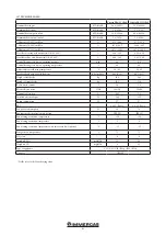
Info menu
Menu item
Description
Unit of measurement
P01
Flame current
μA
P02
Flow NTC probe temperature reading
°C / °F
P03
Return NTC probe temperature reading
°C / °F
P04
DHW NTC probe temperature reading (if installed)
°C / °F
P05
System water flow
l/minute
P06
Operating power
%
P07
Fan speed requested by the system
RPM / 50
P08
Current fan speed
RPM / 50
P09
Flue NTC probe temperature reading
°C / °F
P10
Common flow probe temperature reading (if installed)
or boiler flow probe (based on the system’s configuration)
°C / °F
P11
External probe temperature reading (if installed)
°C / °F
P12
Not used
-
P13
Flow temperature requested by the system in heating
°C / °F
P14
Flow temperature requested by the system in DHW
°C / °F
P15
Not used
-
P16
Number of burners on in simple cascade mode
no.
P17
Number of displays on
no.
2.7 INFO MENU.
Press and hold down "B" to access the info menu
containing all of the various information relative
to boiler operation.
Once you are inside the menu, you will mo-
mentarily see the parameter number followed
by the value.
To scroll through the various parameters, press
b and - (ref. 2 fig. 2-1).
To exit the menu, press and hold "B" down again.
While the parameter value is being displayed it
is possible to momentarily see the relative code
again by pressing button "A". The viewable pa-
rameters are listed in the following tables.
2-10
Содержание VICTRIX PRO 35 2ErP
Страница 1: ...IE Instruction and warning book VICTRIX PRO 35 55 2 ErP 1 041662ENG...
Страница 2: ......
Страница 38: ...38 3 15 1 6 8 9 9 12 12 10 11 13 13 13 13 A A Rif A 7 7 Ref A...
Страница 49: ...49...
Страница 50: ...50...
Страница 51: ...51...


