background image

10

(A)

(B)

1-9

1.12 IMMERGAS FLUE SYSTEMS.

Immergas can supply various solutions for flue-

ing and air supply.

Attention: the boiler must be installed ex-

clusively with an original Immergas “Green 

Range” inspectionable air intake system and 

fumes extraction system made of plastic, with 

the exception of the C6 configuration, as re-

quired by the regulations in force.
The plastic pipes cannot be installed outdoors, 

for lengths longer than 40 cm, without suitable 

protection from UV rays and other atmos-

pheric agents.
This system can be identified by an identifi-

cation mark and special distinctive marking 

bearing the note: “only for condensing boilers”.

• 

Configuration type B, open chamber and fan 

assisted. 

The boiler leaves the factory with type 

“B

23

” configuration.

  Air intake takes place directly from the envi-

ronment in which the boiler is installed via 

relevant slots made in the back of the boiler 

and flue exhaust in the individual flue or to the 

outside. Boiler with this type of configuration 

are classified as type B

23

 (in accordance with 

standard EN 297 and relative standards in 

force).

  With this configuration:
  -  air intake takes place directly from the room 

in which the appliance is installed;

  -  the flue exhaust must be connected to its own 

individual flue or channelled directly into the 

external atmosphere.

  - Type B open chamber boilers must not be 

installed in places where commercial, artisan 

or industrial activities take place, which use 

products that may develop volatile vapours 

or substances (e.g. acid vapours, glues, paints, 

solvents, combustibles, etc.), as well as dusts 

(e.g. dust deriving from the working of wood, 

coal fines, cement, etc.), which may be harm-

ful for the components of the appliance and 

jeopardise operation.

• 

Type C configuration, sealed chamber and 

fan assisted. 

The boiler leaves the factory with 

"B

23

" configuration, to change the configuration 

of the boiler to type "C" (sealed chamber and 

fan assisted), disassemble the 80 Ø adapter, the 

bracket and the gasket present on the boiler 

cover and install the designated flue.

• Coupling extension pipes and concentric 

elbows. To install push-fitting extensions with 

other elements of the flue, proceed as follows: 

Install the concentric pipe or elbow with the 

male side (smooth) on the female section 

(with lip seal) to the end stop on the previously 

installed element in order to ensure sealing 

efficiency of the coupling.


Attention:

 if the exhaust terminal and/or 

concentric extension pipe needs shortening, 

consider that the internal duct must always 

protrude by 5 mm with respect to the external 

duct.

• 

N.B.:

 for safety purposes, do not obstruct the 

boiler intake-exhaust terminal, even temporar-

ily.

• 

N.B.:

 when installing horizontal pipes, a min-

imum inclination of 3% must be maintained 

and a section clamp with pin must be installed 

every 3 metres.

• 

Maximum extension. 

Each individual compo-

nent has a resistance corresponding to a certain 

length in metres of pipe with the same diameter 

(par. 1.13). With installations that involve using 

various types of parts, deduct the length of 

the added part from the maximum admissible 

length of the kit.

  Example: if you need to add a 90° bend to 

a concentric system 125 Ø you will need to 

deduct 1.9 m from the maximum admissible 

length.

• 

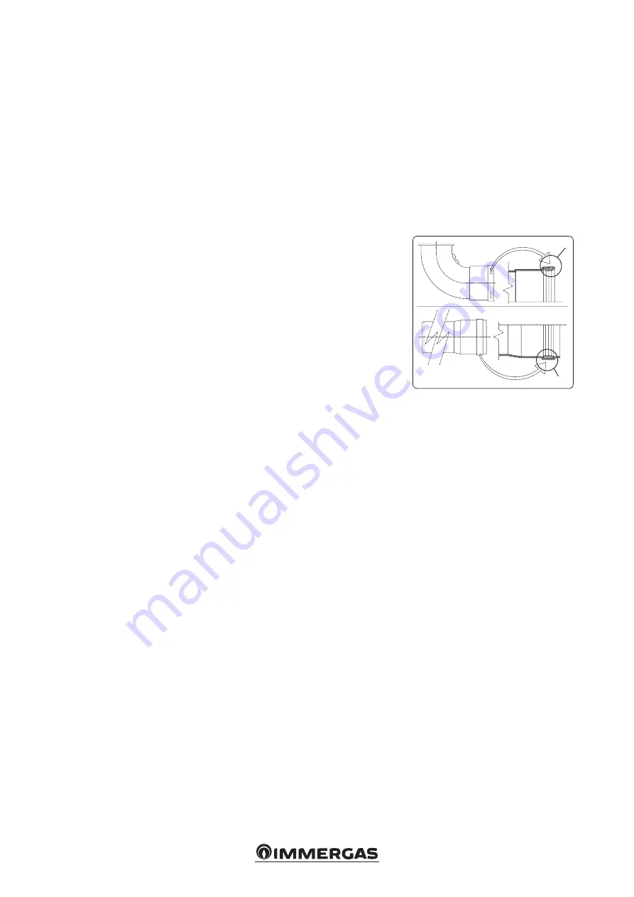
Positioning of the gaskets (black) for “green 

range” flue extraction systems.

 Position the 

gasket correctly (for bends and extensions) 

(Fig. 1-9):

  - gasket (A) with notches, to use for bends;
  -  gasket (B) without notches, to use for exten-

sions;

 N.B.:

 if component lubrication (already carried 

out by the manufacturer) is not sufficient, re-

move the residual lubricant using a dry cloth, 

then to ease fitting coat the parts with talc, 

supplied in the kit.

Содержание VICTRIX PRO 35 2ErP

Страница 1: ...IE Instruction and warning book VICTRIX PRO 35 55 2 ErP 1 041662ENG...

Страница 2: ......

Страница 3: ...in the regulations in force and principles of good practice In compliance with legislation in force the systems must be designed by qualified professionals within the dimensional limits established b...

Страница 4: ...9 Restoring central heating system pressure 26 2 10 System drainage 26 2 11Anti freeze protection 26 2 12Case cleaning 26 2 13Decommissioning 26 3 Boiler commissioning initial check 27 3 1 Hydraulic...

Страница 5: ...ts or fixing template to fix the appliance to the wall they only ensure adequate support if inserted correctly according to technical standards in walls made of solid or semi hollow brick or block In...

Страница 6: ...temperature 5 C The boiler comes standard with an anti freeze function that ac tivates the pump and burner when the system water temperature in the boiler falls below 5 C The anti freeze function is...

Страница 7: ...igned to operate with combustible gas free of impurities otherwise it is advisable to fit special filters upstream of the appliance to restore the purity of the fuel Storage tanks in case of supply fr...

Страница 8: ...nce is reached only when it is correctly connected to an efficient earthing system as specified by current safety standards Attention Immergas S p A declines any respon sibility for damage or physical...

Страница 9: ...s Thermoregulation electrical connection Fig 1 4 Thermoregulation electrical connections must be carried out on the boiler terminal board eliminating jumper X40 Thermostat or On Off environment chrono...

Страница 10: ...pe C configuration sealed chamber and fan assisted The boiler leaves the factory with B23 configuration to change the configuration of the boiler to type C sealed chamber and fan assisted disassemble...

Страница 11: ...mplete with vertical exhaust 80 Exhaust m 3 DUCT TYPE Equivalent length in m of concentric pipe 80 125 Concentric pipe 80 125 m 1 1 0 m Concentric bend 90 80 125 1 9 m Concentric bend 45 80 125 1 4 m...

Страница 12: ...in order to ensure sufficient space to carry out the tests required by law upon commissioning External grid The intake exhaust terminal if properly installed is pleasant to look at on the outside of...

Страница 13: ...ng the previously disassembled sheet steel plate 3 Installation of the fake aluminium tile replace the tiles with the aluminium sheet 5 shaping it to ensure that rainwater runs off Position the fixed...

Страница 14: ...with this configuration can be extended up to a max measurement of 24 0 m with Victrix Pro 35 2ErP and 30 0 m with Victrix Pro 55 2ErP including the terminal Using the 80 vertical terminal for direct...

Страница 15: ...has been fitted This will ensure sealing and joining of the elements making up the kit Horizontal kit 80 with exhaust in flue Kit assembly Fig 1 21 install the 80 bend 1 with the male side smooth full...

Страница 16: ...compiled at the end of work and on commissioning of the ducted system The instructions in the project or technical report must likewise be followed in cases provided for by the standard and current te...

Страница 17: ...pump always runs at maximum speed Pump release If after a prolonged period of inactivity the circulation pump is blocked unscrew the front cap and turn the motor shaft using a screwdriver Take great...

Страница 18: ...ter 13 Ignition electrode 14 Air pressure switch 15 Flue probe 16 Condensing module air vent valve 17 Fumes hood 18 Sample points air A flue gas F 19 Heat exchanger safety thermal fuse 20 Manual air v...

Страница 19: ...aker switches andofthethermometer notsuppliedasstandard with the boiler must be set up as described in the installation instructions in compliance with theprovisionsofthe R collection Wheneverthe gene...

Страница 20: ...1 13 Zone 2 central heating circuit pump CMI 2 14 Zone 3 direct circuit pump CD 15 Storage tank unit feeding pump 16 Zone 1 safety thermostat CMI 1 17 Zone 2 safety thermostat CMI 2 19 Fuel shut off...

Страница 21: ...anti freeze is not used b shut off all electrical water and gas supplies N B in the case of maintenance interventions on the boiler that lead to the closure of one or both system cut off cocks the boi...

Страница 22: ...25 Summer mode 2 5 USING THE BOILER Before ignition make sure that the system is full of water checking that the manometer 5 indicates a base value at which the system has been designed and calculate...

Страница 23: ...us setting 2 4 2 5 Stand by mode by pressing buttons A and C at the same time it is possible to place the boiler in stand by In this mode the boiler is considered powered on but not active Accordingly...

Страница 24: ...ure detection incorrect in stand by With the boiler in stand by the board detects an anomalous difference between the NTC probe flow and return temperatures The error may be caused by a failure in one...

Страница 25: ...probe 2 1 0E46 FlueNTCprobeoutside theoperatingrange The board detects an open contact on the flue NTC probe 2 1 0E81 Flow and return NTC probe temperature detection incorrect in stand by With the boi...

Страница 26: ...frequently filling must be carried out with suitably treated water to eliminate hardness that can cause lime scale 2 12 CASE CLEANING Use damp cloths and neutral detergent to clean the boiler casing N...

Страница 27: ...ll adjustment devices seal the gas flow rate regulation devices if settings are modified check sealing efficiency of water circuits check ventilation and or aeration of the instal lation room where pr...

Страница 28: ...iler configuration jumper Y1 Gas valve Configure the corresponding parameters when connecting in simple cascade or when con necting in system side flow probe or D H W pump 1 External reset optional 2...

Страница 29: ...ectronic board A4 Display board B1 Flow probe B1 2 System side flow probe optional B2 Domestic hot water probe optional B4 External temperature probe optional B5 Return probe B10 Flue probe B25 System...

Страница 30: ...r probe NTC optional B4 External probe optional M2 Plant CH pump optional M30 3 way valve optional Note probe B1 2 B2 B4 Connection cable diameter 3 7 mm Cable section 0 5 1 5 mm2 1 External relay opt...

Страница 31: ...at the radiator valves are not closed and also the functionality of the pump In addition check that the exchanger safety thermostat has not intervened If it has check the integrity of the module and c...

Страница 32: ...io It defines the boiler s modulation ratio Do not modify 0 100 10 P13 Boiler power Used to calculate the boiler power in the event of simple cascade 0 255 kW 35 kW 35 55 kW 50 P14 External probe curv...

Страница 33: ...nes the unit of measure on the display whether metric or Imperial 0 127 C kW 128 256 F kBTu h 0 P32 Set Resc Min Limits the minimum value of the heating set The parameter takes priority in relation to...

Страница 34: ...tor To increase the CO2 value turn the adjustment screw 3 in a clockwise direction and vice versa to decrease it Calibration of maximum CO2 When you finish the minimum CO2 adjustment turn the boiler o...

Страница 35: ...d to terminals S1 and S2 and parameter P38 must be set up whereas the pump must be connected to termi nals C and D If there is a DHW circuit it can be connected via an external 3 way to be connected t...

Страница 36: ...every two years regardless of their state of wear Check that the burner is intact that it has no deformations or cuts and that it is properly fixed to the combustion chamber lid otherwise it must be r...

Страница 37: ...the central hooks and then slide it downwards take the two clamping screws out 4 from the control panel with their rings 5 press the two side hooks 7 and tilt the control panel 6 remove the lower grid...

Страница 38: ...38 3 15 1 6 8 9 9 12 12 10 11 13 13 13 13 A A Rif A 7 7 Ref A...

Страница 39: ...690 2 38 4510 29 0 24940 3 13 4570 2 30 4380 28 5 24469 3 07 4500 2 26 4310 27 0 23220 2 92 4320 2 14 4120 26 0 22360 2 81 4200 2 06 4000 25 0 21500 2 71 4070 1 99 3870 24 0 20640 2 60 3950 1 91 3750...

Страница 40: ...0 10 CO with 0 O2 at Nom Min Q Nom Min ppm 157 1 184 1 NOX at 0 of O2 at Q Nom Min mg kWh 43 17 43 21 Flue temperature at nominal output C 52 53 Flue temperature at minimum output C 48 48 METHANE G20...

Страница 41: ...4 4 4 4 Central heating circuit max operating temperature C 90 90 Adjustable central heating temperature C 20 85 20 85 Head available with 1000 l h flow rate kPa m H2 O 60 1 6 13 60 1 6 13 Weight of f...

Страница 42: ...N Serial Number CHK Check Cod PIN PIN code Type applianceconfiguration ref CENTR1749 Qnw min Minimum DHW heat input Qn min CH minimum heat input Qnw max DHW maximum heat input Qn max CH maximum heat i...

Страница 43: ...ns 60 C on return and 80 C on flow Low temperature mode for condensation Boilers means 30 C for low temperature boilers 37 C and for other appliances 50 C of return temper ature Model s Victrix Pro 55...

Страница 44: ...easonal room heating yield s 91 Domestic hot water production yield wh Parameter value Yearly energy consumption for the heating function QHE 86 7 GJ Yearly electricity consumption for the domestic ho...

Страница 45: ...r Supplementary heat pump From fiche of heat pump Solar contribution and Supplementary heat pump Select smaller value Boiler and supplementary heat pump installed with low temperature heat emitters at...

Страница 46: ...che of heat pump The energy efficiency of the package of products provided far in this fiche may not correspond to its actual energy efficiency once installed in a building as the efficiency is influe...

Страница 47: ...contribution From fiche of solar device 1 I 2 1 1 x I 10 x II III I Auxiliary electricity 3 G F E D C B A A A A 27 27 27 28 27 27 27 28 30 30 30 32 33 34 35 36 36 37 38 40 39 50 55 60 65 75 80 85 100...

Страница 48: ...gy efficiency under colder and warmer climate conditions Colder 0 2 x Warmer 0 4 x Declared load profile Solar contribution From fiche of solar device 1 ___ 2 1 1 x ___ 10 x ___ ____ ____ Auxiliary el...

Страница 49: ...49...

Страница 50: ...50...

Страница 51: ...51...

Страница 52: ...mmergas S p A 42041 Brescello RE Italy Tel 0522 689011 Fax 0522 680617 Certified company ISO 9001 This instruction booklet is made of ecological paper Cod 1 041662ENG rev ST 003517 000 12 18 Inglese p...

Отзывы: