31
3-2
2
3
4
8
5
6
1
7
CH ON
9
10
INS
TALLER
US
ER
MAINTEN
AN
CE TECHNI
CI
AN
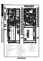
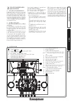
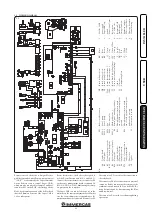
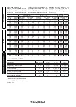
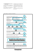
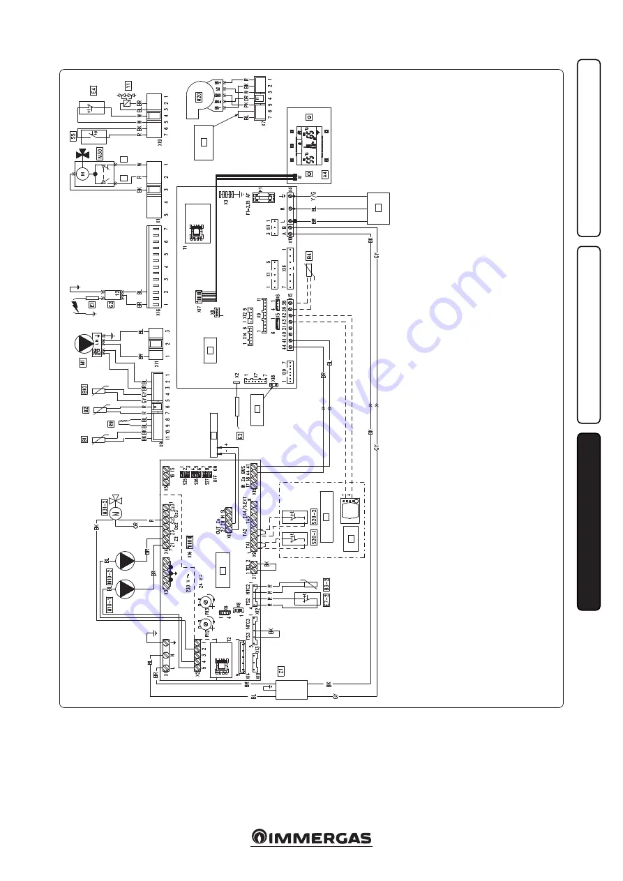
3.2 WIRING DIAGRAM.
Ke
y:
A4
-
D
isp
la
y b
oa
rd
B1
-
Fl
ow p
ro
be
B2
-
D
om
es
tic h
ot w
at
er p
ro
be
B3-2
-
Zo
ne 2 m
ix
ed fl
ow p
ro
be
B4
-
Ext
er
na
l p
ro
be (o
pt
io
na
l)
B10
-
Fl
ue p
ro
be
E1
-
Ig
ni
tio
n e
lec
trode
s
E2
-
D
et
ec
tio
n e
lec
trode
E4
-
Sa
fety t
her
m
os
ta
t
E7-2
-
Zo
ne 2 l
ow t
em
per
at
ur
e
sa
fet
y t
he
rm
osta
t
F1
-
Ph
as
e f
us
e
G2
-
Ig
ni
ter
M1
-
Bo
iler ci
rcu
la
to
r p
um
p
M10-1
-
Zo
ne 1 p
um
p
M10-2
-
Zo
ne 2 p
um
p
M20
-
Fa
n
M30
-
Th
re
e-w
ay v
al
ve
M31-2
-
M
ixi
ng v
al
ve z
on
e 2
R9
-
Re
tur
n p
rob
e un
ab
ling
re
sis
ta
nc
e
R12
-
Fl
ow a
dj
us
tm
en
t t
rim
m
er m
ix
ed
zo
ne 2 (w
ith o
pt
io
na
l ext
er
na
l p
ro
be
pr
es
en
t)
R13
-
Fl
ow a
dj
us
tm
en
t t
rim
m
er m
ix
ed
zo
ne 3 (w
ith o
pt
io
na
l ext
er
na
l p
ro
be
an
d z
on
es k
it p
re
sen
t)
S5
-
Sys
tem p
re
ssu
re s
w
itc
h
S25
-
Bo
ar
d s
ett
in
g s
ele
ct
or
S26
-
Bo
ar
d s
ett
in
g s
ele
ct
or
S27
-
Bo
ar
d s
ett
in
g s
ele
ct
or
S20-1
-
Ro
om t
her
m
os
ta
t z
on
e 1
S20-2
-
R
oo
m t
her
m
os
ta
t z
on
e 2
T1
-
Bo
iler b
oa
rd l
ow v
ol
ta
ge f
ee
der
T2
-
Zo
ne
s c
on
tro
l u
ni
t l
ow v
ol
ta
ge
feed
er
Y1
-
G
as v
al
ve
Z1
-
An
tija
m
m
in
g fi
lter
BK
-
Bl
ac
k
BL
-
Bl
ue
BR
-
Br
ow
n
G
-
Gr
een
GY
-
Gr
ey
G/Y
-
Gr
een-Y
ell
ow
O
R
-
O
ra
nge
P
-
Pu
rp
le
PK
-
Pin
k
R
-
Re
d
W
-
W
hi
te
Y
-
Ye
llo
w
Remote controls: the boiler is designed for use
with the Comando Amico Remoto remote control
V2
(CAR
V2
) or alternatively the Super Comando
Amico Remoto remote control (Super CAR),
which must be connected to clamps 42 and 43 of
connector X15 on the P.C.B., observing polarity.
Note:
for optimal operation of the boiler, check
that the Firmware version of the Super CAR is
1.03 or subsequent.
Room thermostats: the boiler is designed to
use the Room Thermostats (S20-1 and S20-2).
Connect the room thermostats to connector X9
on the zones management board, terminals 1-2
(S20-1) AND 3-4 (S20-2) eliminating the jump-
ers present on the connector.
The Super CAR can control the zone set as the
main one on the zones management board. In this
case the room thermostat corresponding to the
main zone must not be connected to connector X9.
The connector X5 is used for the connection to
the relay board.
The connector X6 is for connection to a personal
computer. Before connecting the computer the
communication between the two boiler P.C.B.s
must be interrupted by disconnecting the Blue
and Brown wires.
The connector X8 is used for software updating
operations.
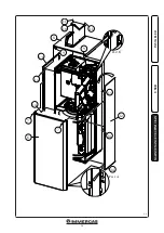
1
-
230 V
ac 50 H
z
po
we
r sup
pl
y
2
-
Su
per CAR (O
p-
tio
nal
)
3
-
Zo
ne
s c
on
tro
l r
oo
m
th
er
m
osta
ts
4
-
N°. o
f f
an r
evs.
5
-
In
te
gr
at
ed P
.C.B
6
-
S
ta
tu
s sig
na
l
7
-
St
or
age t
an
k c
on
-
fig
ur
at
io
n j
um
pe
r
8
-
Zo
ne
s c
on
tro
l u
ni
t
9
-
D
om
es
tic h
ot w
at
er
10
-
C
en
tra
l h
ea
tin
g

