30
3-1
INS
TALLER
US
ER
MAINTEN
AN
CE TECHNI
CI
AN
3
BOILER COMMISSIONING
(INITIAL CHECK)
To commission the boiler:
- make sure that the type of gas used corresponds
to boiler settings;
- check connection to a 230V-50Hz power
mains, correct L-N polarity and the earthing
connection;
- make sure the central heating system is filled
with water and that the pressure gauge indicates
a pressure of 1-1.2 bar.
- check that the the air vent valve cap is open and
that the system is well deaerated;
- switch the boiler on and check correct ignition;
- check the ∆p gas values in domestic hot water
and central heating modes;
- check the CO
2
in the fumes at maximum and
minimum flow rate;
- check activation of the safety device in the event
of no gas, as well as the relative activation time;
- check the intervention of the main switch
located upstream of the boiler and in the boiler;
- check that the intake and/or exhaust terminals
are not blocked;
- ensure activation of all adjustment devices;
- seal the gas flow rate regulation devices (if set-
tings are modified);
- check the production of domestic hot water;
- check sealing efficiency of water circuits;
- check ventilation and/or aeration of the instal-
lation room where provided.
If even only a single safety check offers a negative
result, do not commission the system.
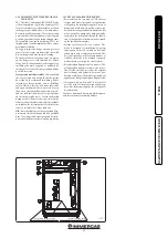
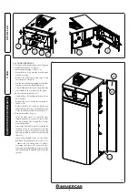
Risk of material damage after using sprays and
liquids to search for leaks.
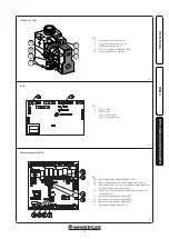
Leak sprays and liquids clog the reference hole
PR (Part. 4 Fig. 3-3) of the gas valve, damaging
it irreparably.
During installation and maintenance, do not
use spray or liquids in the upper area of the gas
valve (side referring to the electric connections).
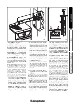
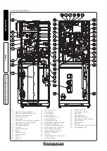
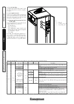
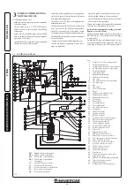
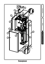
3.1 PLUMBING DIAGRAM.
Key
1 - Stainless steel coil for storage tank
2 - System draining valve
3 - Storage tank unit return one-way valve
4 - Polyphosphate dispenser (optional)
5 - System filling valve
6 - 3 bar safety valve
7 - Manifold draining valve
8 - Condensate drain trap
9 - Gas valve
10 - Gas valve outlet pressure point (P3)
11 - Air intake pipe
12 - Fan
13 - Gas nozzle
14 - Detection electrode
15 - Burner
16 - Condensation module covers
17 - Condensation module
18 - Manual air vent valve
19 - Flue probe
20 - Fumes hood
21 - Air sample point
22 - Flue sample point
23 - Gas ΔP pressure point
24 - Flow probe
25 - Safety thermostat
26 - Ignition electrode
27 - Boiler Circulator
28 - System pressure switch (absolute)
29 - Three-way valve (motorised)
30 - Venturi positive sign P1
31 - Venturi negative sign P2
32 - Air/gas Venturi manifold
33 - System expansion vessel
34 - Vent valve
35 - Hydraulic manifold
36 - Mixing valve mixed zone 2
37 - Mixed zone 2 system circulator
38 - Low temperature safety thermostat
39 - Zone 2 mixed flow probe
40 - Direct zone 1 system circulator
41 - One-way valve direct zone 1
42 - D.H.W. expansion vessel
43 - Cold water inlet cock
44 - Cold water inlet filter
45 - Flow limiter
46 - Cold water inlet non-return valve
47 - 8 bar safety valve
48 - DHW recirculation pump (optional)
49 - Domestic hot water probe
50 - Magnesium anode
51 - Storage tank unit draining valve
RZ2 - Mixed zone 2 system return
MZ2 - Mixed zone 2 system flow
RZ1 - Direct zone 1 system return
MZ1 - Direct zone 1 system flow
G - Gas supply
AC - Domestic hot water outlet
AF - Domestic cold water inlet
RC - Domestic hot water recirculation
RP - Return from solar panels
MP - Flow from solar panels


