background image

19

1-25

INS

TALLER

US

ER

MAINTEN

AN

CE TECHNI

CI

AN

tion, the electric power consumption of the 

circulator pump is reduced further: the energy 

(power) used by the pump decreases according 

to the pressure level and flow rate. With this 

setting, the pump guarantees optimal perfor-

mance in most heating systems, thereby being 

particularly suitable in single-pipe and two-

pipe installations. Any noise of the water flow 

in the pipes, valves and radiators is eliminated 

by reducing the head. Optimal conditions for 

thermal comfort and acoustic well-being.

Programs C (3 lower 4 upper) (ΔP-C) - Con-

stant curve (orange LED).

 The circulator 

pump maintains the pressure level (head) 

constant as the system heat demand decreases 

(flow rate reduction). With these settings, the 

circulator pump is suitable for all floor systems 

where all the circuits must be balanced for the 

same drop in head.

MIN-MAX Program (Blue LED).

 The pump 

is distinguished by adjustable operating curves 

by positioning the selector in any point between 

the Min and Max positions, thereby satisfying 

any installation requirement (from a simple 

single-pipe to more modern and sophisticated 

systems) and always guarantee optimum per-

formance. The precise working point can be 

selected in the entire field of use by gradually 

adjusting the speed.

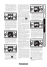
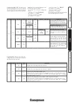
Real time diagnostics:

 a lit LED (in various 

colours) provides information regarding the 

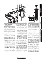
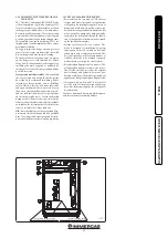
pump operating status, see fig. 1-25


Possible pump release.

 The pump block is 

indicated by a fixed red LED switching on. Turn 

the selector up to the MAX position, discon-

nect and reconnect the power to restart the 

automatic release process. The pump will then 

activate the procedure that will last a maximum 

of 15 minutes and the LED will flash upon each 

restart. It then turns blue for a few seconds and 

goes back to red if the attempt to restart is not 

successful. Once the process is complete, set 

the selector back to the desired curve and if 

the problem has not bee resolved, perform the 

manual release procedure as described below.

  -  Disconnect the power to the boiler (the LED 

switches off). 

  - Close the system flow and return and let the 

pump cool down.

  -  Empty the system circuit via the relative cock.
  - Remove the motor and clean the impeller. 
  - Once unblocked, remount the motor.
  -  Fill the primary circuit; restore boiler power 

and set the desired curve.

 Attention:

  there is a burns hazard due to high 

fluid temperature and pressure. 

Burns hazard 

from coming in contact.

1.23 CIRCULATION PUMP.

Boilers in the “Hercules Condensing ABT 32 3 

ErP” series are supplied with 2 types of circulat-

ing pumps. Set operation modes according to 

one's installation requirements.
• 

Boiler circulator pump. 

The circulating pump 

is not equipped with speed selector. To change 

operation mode, parameter “Pump sp.” in the 

“Configurations” boiler menu must be changed.

  Pump release.

  If the pump should be blocked 

after a long period of inactivity, it must be re-

leased. Loosen the front cap, making sure that 

the liquid that escapes cannot cause injury/

damage to persons/objects and turn the mo-

tor shaft very carefully using a screwdriver so 

as not to damage the latter. Once the pump is 

released, close the vent cap.

• 

Direct and mixed zone circulator. 

The pump 

is ideal for the requirements of each central 

heating system in a domestic and residential 

environment. In fact, the pump is equipped 

with electronic control that allows to set ad-

vanced functions.

Adjustments.

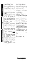
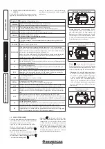
 Turn the selector and set it on 

the desired curve to adjust the circulator pump.

Program

LED

P 1 lower (ΔP-V)

P 2 upper (ΔP-V)

green

C 3 lower (ΔP-C) - H=3 m

C 4 upper (ΔP-C) - H=4 m

orange

Min - Max

blue

Program P (1 lower 2 upper) (ΔP-V) - Pro-

portional curve


(green LED).

 This allows 

the pressure level (head) to be proportionally 

reduced as the system heat demand decreases 

(flow rate reduction). Thanks to this func-

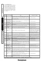
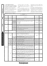
Circulating pump 

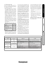
LED

Description

Diagnostics

Remedy

LED steady on

Pump 

noisy

Insufficient system pressure, circulating pump 

in cavitation

Restore correct thermal circuit pressure

Presence of foreign matter in the impeller

Remove the motor and clean the impeller

Flashing white LED

Noises during cir-

culation of the heat 

transfer fluid

Presence of air in the system

Vent the system

LED steady on

Flow rate too high

Reduce rotation speed

LED off

The circulator does 

not work

Power outage

Ensure the boiler is correctly powered, ensure 

the circulator is correctly powered

Faulty circulating pump

Replace the circulating pump

Red LED

Rotor seized

Remove the motor and clean the impeller

Insufficient power supply voltage

Check boiler power supply voltage

Содержание Hercules Condensing ABT 32 3 ErP

Страница 1: ...HERCULES CONDENSING ABT 32 3 ERP Instruction and recommendation booklet IE 1 037972ENG ...

Страница 2: ......

Страница 3: ...established by the Law Installation and maintenance must be performed in compliance with the regulations in force according to the manufacturer s instructions and by professionally qualified staff intending staff with specific technical skills in the plant sector as envisioned by the Law Improper installation or assembly of the Immergas appliance and or components accessories kit and devices can c...

Страница 4: ...Description of functioning states 24 2 5 Using the boiler 24 2 6 Troubleshooting 26 2 7 Boiler shutdown 27 2 8 Restore central heating system pressure 27 2 9 System draining 27 2 10Cylinder draining 27 2 11Antifreeze protection 27 2 12Case cleaning 28 2 13Decommissioning 28 2 14Parameters information and zones menu 28 3 Boiler commissioning initial check 30 3 1 Plumbing diagram 30 3 2 Wiring diagr...

Страница 5: ...ept out of the reach of children If the appliance is installed in side or between cabinets ensure sufficient space for normal servicing therefore it is advisable to leave clearance of at least 30 cm on the right of the boiler in order to open the lateral hatch and a space of 3 cm between the remaining sides of the boiler and the sides of the cabinet Leave adequate space above the boiler for possib...

Страница 6: ... 1 mixed zone 2 system return MZ2 G 1 mixed zone 2 system flow RZ1 G 3 4 direct zone 1 system return MZ1 3 4 direct zone 1 system flow G Gas supply G 1 2 AC DHW output G 3 4 AF DHW inlet G 3 4 RC Recirculation G 3 4 optional RP Return to solar panels G 3 4 optional MP Flow from solar panels G 3 4 optional SC Condensate drain minimum internal diameter Ø 13 mm ...

Страница 7: ...t be connected to a draining funnel Otherwise the manufactur er declines any responsibility in case of flooding if the drain valve cuts in Attention the manufacturer declines all liability in the event of damage caused by the inclusion of automatic filling that is not its own brand In order to meet the system requirements es tablished by the technical regulation in force in relation to the polluti...

Страница 8: ... chrono thermostat is fed directly by the boiler by means of the same 2 wires used for transmitting data between boiler and device Important if the CARV2 or Super CAR is used the climatic heat adjustment function must be excluded i e setting it in the On Off mode CARV2 Super CAR or On Off room chrono thermostat electrical connection Optional The operations described below must be performed after h...

Страница 9: ...on clamps 38 and 39 on the boiler P C B Fig 3 2 Direct Zone Check The correlation between system flow temperature and external tem perature is determined by the parameters set in menu M5 under item P66 according to the curves represented in the diagram Fig 1 6 Mixed Zone Check The correlation between flow temperature to the system and external temperature is determined by the position of the trimm...

Страница 10: ... pass through the pipe and therefore varies according to applica tions for air intake or flue exhaust Each single component has a resistance corresponding to a certain length in metres of pipe of the same diameter the so called equivalent length can be obtained from the ratio between the relative Resistance Factors All boilers have an experimentally obtainable maximum Resistance Factor equal to 10...

Страница 11: ...Intake and Exhaust 16 3 m 2 5 Intake m 18 7 Exhaust m 4 9 m 7 7 Exhaust m 13 6 Concentric vertical intake exhaust terminal Ø 60 100 Intake and Exhaust 9 m 1 4 Intake m 10 3 Exhaust m 2 7 m 4 3 Exhaust m 7 5 Pipe Ø 80 m 1 Intake 0 87 m 0 1 Intake m 1 0 Exhaust m 0 4 m 0 4 m 0 5 Exhaust 1 2 m 0 2 Exhaust m 1 0 Complete intake terminal Ø 80 m 1 Intake 3 m 0 5 Intake m 3 4 Exhaust m 0 9 m 1 4 Intake t...

Страница 12: ...ventilated rooms the flue gas exhaust must be connected to its own individual flue or ducted directly into the external atmosphere Type B open chamber boilers must not be installed in places where commercial artisan or industrial activities take place which use products that may develop volatile vapours or substances e g acid vapours glues paints solvents combustibles etc as well as dusts e g dust...

Страница 13: ...ontal m in cluding the terminal with grid and excluding the concentric bend leaving the boiler This configurationcorrespondstoaresistancefactor of 100 In this case the special extensions must be requested Immergas also provides a Ø 60 100 simplified terminal which in combination with its exten sion kits allows you to reach a maximum exten sion of 11 9 metres Horizontal intake exhaust kit Ø 80 125 ...

Страница 14: ...ength of 14 4 m including the terminal This configuration corresponds to a resistance factor of 100 In this case specific extensions must be requested Vertical kit with aluminium tile Ø 80 125 Kit assembly Fig 1 16 to install the kit Ø 80 125 one must use the flanged adapter kit in order to install the flue system Ø 80 125 Install the flanged adaptor 2 on the central hole of the boiler positioning...

Страница 15: ...smooth in the female side of the bend 5 up to the end stop ensuring that the internal and external wall sealing plates are fitted Fit the exhaust pipe 9 with the male side smooth to the female side of the bend 5 up to the end stop making sure that the internal wall sealing plate has been fitted this will ensure sealing and joining of the elements making up the kit Installation clearances Fig 1 19 ...

Страница 16: ... the external pipe must be fitted on the adaptor until it stops 1 N B to encourage the removal of possible condensate forming in the exhaust pipe tilt the pipes towards the boiler with a minimum slope of 1 5 Mount the cover A complete with adaptor 1 and caps 6 on the wall and assemble the flue system to the ducting system N B version Ø 125 only before assembly check the gaskets are in the right po...

Страница 17: ...h of the Ø 80 rigid ducting vertical section is equal to 30 m This length is obtained considering the complete Ø 80 exhaust terminal 1m of Ø 80 pipe in exhaust two 90 Ø 80 bends on the boiler outlet 1 16 CONFIGURATION TYPE B OPEN CHAMBER AND FAN ASSISTED FOR INDOORS The appliance can be installed inside buildings in 23 or B53 mode in this case all technical rules and national and local regulations...

Страница 18: ...perations turn on the circu lating pump at intervals using the main switch on the control panel Vent the circulation pump by loosening the front cap and keeping the motor running and assuring that the liquid that escapes cannot cause injury damage to persons objects Tighten the cap after the operation Attention to carry out the filling procedure correctly activate the automatic vent function see p...

Страница 19: ...he motor and clean the impeller Once unblocked remount the motor Fill the primary circuit restore boiler power and set the desired curve Attention there is a burns hazard due to high fluid temperature and pressure Burns hazard from coming in contact 1 23 CIRCULATION PUMP Boilers in the Hercules Condensing ABT 32 3 ErP series are supplied with 2 types of circulat ing pumps Set operation modes accor...

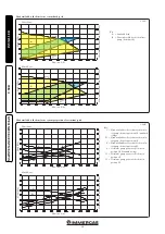
Страница 20: ...system with circula tor pump selector in position C4 standard setting D Head available to the system with circula tor pump selector in position C3 E Head available to the system with circula tor pump selector in position P2 F Circulator pump power with selector in position C4 standard setting G Circulator pump power with selector in position C3 H Circulator pump power with selector in position P2 ...

Страница 21: ...brackets and slide the cylinder outwards on the relevant guides Work in reverse order to assemble the storage tank unit N B have the efficiency of the storage tank Mag nesium Anode checked annually by a qualified firm The storage tank unit is prepared for intro duction of the domestic hot water pump fitting 1 25 KITS AVAILABLE ON REQUEST Recirculation kit on request The boiler storage tank unit is...

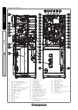
Страница 22: ...ostat mixed zone optional 7 Flow probe mixed zone optional 8 Zone 2 pump optional 9 Mixing valve optional 10 Flue probe 11 Condensation module 12 Burner 13 Ignition electrode 14 Detection electrode 15 Venturi 16 Gas nozzle 17 Fan 18 Cold water inlet cock 19 8 bar safety valve 20 Air intake pipe 21 3 bar safety valve 22 D H W expansion vessel 23 System filling valve 24 Condensate drain trap 25 Poly...

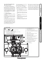
Страница 23: ... sunlight etc the appliance power cable must not be re placed by the user in the event of damage to the cable switch off the appliance and contact exclusively quali fied staff for replacement if the appliance is not to be used for a certain period disconnect the main power switch N B the temperatures indicated by the display have a tolerance of 3 C due to environmental conditions that cannot be at...

Страница 24: ... control status of the boiler flow temperature for room central heat ing SET In the presence of the external probe optional replace the SET item The value that appears is the correction of the flow temperature with respect to the functioning curve set by the external probe See OFFSET in the graphs of the external probe Fig 1 6 1 7 F8 System deaeration in progress During this phase which lasts 18 h...

Страница 25: ...RR CM connection error symbol will bedisplayedontheSuperCAR TheSuperCAR remote control is however constantly powered thus stored programs are not lost Domestic hot water priority function By pressing button B the D H W priority func tionisactivated whichismarkedbythesymbol 15 switching off on the display 24 Attention the disabled function keeps the wa ter contained in the storage tank at a tempera...

Страница 26: ...ure gauge 1 that the system pressure is between 1 1 2 bar and restore the correct pressure if necessary 12 Storage tank probe anomaly The board detects an anomaly on the storage tank probe The boiler cannot produce domestic hot water 15 Configuration error If the board detects an anomaly or incongruity on the electric wiring the boiler will not start If normal conditions are restored the boiler re...

Страница 27: ...t having to be reset 1 47 Burner power limitation Should flue high temperature be detected the boiler reduces power sup plied so as not to damage it 1 1 If the shutdown or fault persists contact an authorised firm e g Authorised Technical After Sales Service 2 7 BOILER SHUTDOWN Switch the boiler off by pressing the but ton disconnect the onmipolar switch outside of the boiler and close the gas coc...

Страница 28: ...to 5 and on indicator 7 the relative error code By pressing button D repeatedly it is possible to view the function ing time and the number of ignitions at which the anomaly occurred M1 information menu This menu contains the various information relative to boiler functioning Key 1 Gas cock 2 Cold water inlet cock 3 System filling valve 2 12 CASE CLEANING Use damp cloths and neutral detergent to c...

Страница 29: ...emains on for 5 seconds after the last operation performed ON The display is always lit up OFF The display only lights up when the controls are accessed and remains on for 5 seconds after the last operation performed P32 D C P32 B D C ITALIANO D x select C All descriptions are given in Italian A1 Default All descriptions are given in alphanumeri cal format P33 D C OFF Default D x select C In winte...

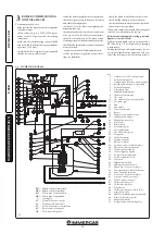
Страница 30: ...pray or liquids in the upper area of the gas valve side referring to the electric connections 3 1 PLUMBING DIAGRAM Key 1 Stainless steel coil for storage tank 2 System draining valve 3 Storage tank unit return one way valve 4 Polyphosphate dispenser optional 5 System filling valve 6 3 bar safety valve 7 Manifold draining valve 8 Condensate drain trap 9 Gas valve 10 Gas valve outlet pressure point ...

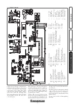
Страница 31: ... for use withtheComandoAmicoRemotoremotecontrol V2 CARV2 or alternatively the Super Comando Amico Remoto remote control Super CAR which must be connected to clamps 42 and 43 of connector X15 on the P C B observing polarity Note for optimal operation of the boiler check that the Firmware version of the Super CAR is 1 03 or subsequent Room thermostats the boiler is designed to use the Room Thermosta...

Страница 32: ...hese adjustments must be made with reference to the type of gas used following that given in the table Par 3 19 3 5 CALIBRATION OF NUMBER OF FAN REVS Attention Verification and calibration is neces sary in the case of transformation to other types of gas in the extraordinary maintenance phase with replacement of the PCB air gas circuit com ponents or in the case of installations with fume extracti...

Страница 33: ...obe 16 Mixed zone flow temperature adjustment trimmer with external probe 17 Board functioning status signal LED 18 Board functioning status signal LED 19 Board functioning status signal LED 20 Board power supply signal LED SIT 848 Gas Valve Key 1 Gas valve inlet pressure point 2 Gas valve outlet pressure point 3 Off Set adjustment screw 4 Pressure regulator connection PR 12 Outlet gas flow rate r...

Страница 34: ...ternal probe optional it defines the maximum flow temperature With the external probe present it defines the maximum flow temperature corresponding to operation with minimum external temperature see graph Fig 1 6 it can be set between 50 C and 85 C N B to continue one must confirm the parameter press D or exit adjustment P66 by pressing C 85 C P66 C With the external probe present it defines at wh...

Страница 35: ...ut domestic hot water has a sufficient temperature the boiler does not switch on P72 AUTO OFF 09 L M 12 L M 15 L M This function does not affect the correct functioning of this boiler model AUTO RELE1 optional RELE1 0 Relay 1 not used RELE1 1 RELE1 1 In a system divided into zones relay 1 controls the main zone RELE1 2 The relay signals the intervention of a boiler block Can be coupled to an exter...

Страница 36: ...iler off and then on again using the Stand by button 3 11 PUMP ANTI BLOCK FUNCTION The boiler has a function that starts the pump at least once every 24 hours for the duration of 30 seconds in order to reduce the risk of the pump becoming blocked due to prolonged inactivity 3 12 THREE WAY ANTI BLOCK FUNCTION Both in domestic hot water and in domestic hot water central heating phase the boiler is e...

Страница 37: ...ts and the lid are intact and perfectly efficient otherwise replace them In any case the gaskets must be replaced at least every two years regardless of their state of wear Check that the burner is intact that it has no deformations or cuts and that it is properly fixed to the combustion chamber lid otherwise it must be replaced Visually check that the water safety valves drain is not blocked Chec...

Страница 38: ...emove the screw 16 in the top corner of the door 15 Release the door 15 from the bracket just released from the screw 16 bending it out wards and sliding it off of the lower pin 17 Casing disassembly Fig 3 8 undo the front screws 7 push the front slightly upwards 6 in order to free it from the lower fixing slots and pull it towards yourself detail A remove the front half cover 8 loosening the inte...

Страница 39: ...39 3 8 6 7 7 14 14 14 14 14 13 9 8 11 11 10 12 9 Part B Part A INSTALLER USER MAINTENANCE TECHNICIAN Part B Part A ...

Страница 40: ...1 14 4 1 92 1 60 16 3 23 0 19780 2 51 1 19 12 1 1 87 1 31 13 4 1 84 1 49 15 2 22 0 18920 2 40 1 11 11 3 1 79 1 22 12 5 1 76 1 39 14 2 21 0 18060 2 29 1 04 10 6 1 71 1 13 11 6 1 68 1 29 13 2 20 0 17200 2 19 0 96 9 8 1 63 1 05 10 7 1 60 1 19 12 2 19 0 16340 2 08 0 89 9 1 1 55 0 97 9 9 1 53 1 10 11 2 18 0 15480 1 97 0 82 8 4 1 47 0 89 9 1 1 45 1 01 10 3 17 0 14620 1 86 0 76 7 7 1 39 0 81 8 3 1 37 0 9...

Страница 41: ...in adjustable central heating temperature C 25 50 System expansion vessel total volume l 10 8 Heating expansion vessel pre charge bar 1 0 Total volume domestic hot water expansion vessel l 4 1 Domestic hot water expansion vessel pre charge bar 3 5 Appliance water content l 6 7 Head available with 1000 l h flow rate in direct zone kPa m H2 O 28 8 2 94 Head available with 1000 l h flow rate in mixed...

Страница 42: ...Sr N Serial Number CHK Check Cod PIN PIN code Type Type of installation ref CEN TR 1749 Qnw min Minimum DHW heat input Qn min CH minimum heat input Qnw max DHW maximum heat input Qn max CH maximum heat input Pn min Minimum heat output Pn max Maximum heat output PMS Maximum system pressure PMW Maximum domestic hot water pressure D Specific flow rate TM Maximum operating temperature NOx Class NOx Cl...

Страница 43: ...consumption Other items At full load elmax 0 031 kW Heat loss in standby Pstby 0 175 kW At partial load elmin 0 014 kW Ignition burner energy consumption Pign 0 000 kW In standby mode PSB 0 005 kW Emissions of nitrogen oxides NOX 47 mg kWh For mixed central heating appliances Stated load profile XL Domestic hot water production efficiency ηWH 80 Daily electrical power consumption Qelec 0 270 kWh D...

Страница 44: ...pplementary heat pump From fiche of heat pump Solar contribution and Supplementary heat pump Select smaller value Boiler and supplementary heat pump installed with low temperature heat emitters at 35 C From fiche of heat pump The energy efficiency of the package of products provided far in this fiche may not correspond to its actual energy efficiency once installed in a building as the efficiency ...

Страница 45: ...p The energy efficiency of the package of products provided far in this fiche may not correspond to its actual energy efficiency once installed in a building as the efficiency is influenced by further factors such as heal loss in the distribution system and the dimensioning of the products in rela tion to building size and characteristics Seasonal space heating energy efficiency of package Seasona...

Страница 46: ...ution From fiche of solar device 1 I 2 1 1 x I 10 x II III I Auxiliary electricity 3 G F E D C B A A A A 27 27 27 28 27 27 27 28 30 30 30 32 33 34 35 36 36 37 38 40 39 50 55 60 65 75 80 85 100 115 123 131 130 150 160 170 163 188 200 213 M L XL XXL 3 2 3 2 The energy efficiency of the package of products provided far in this fiche may not correspond to its actual energy efficiency once installed in...

Страница 47: ...y efficiency under colder and warmer climate conditions Colder 0 2 x Warmer 0 4 x Declared load profile Solar contribution From fiche of solar device 1 _____ 2 1 1 x _____ 10 x _____ ____ ______ Auxiliary electricity 3 G F E D C B A A A A 27 27 27 28 27 27 27 28 30 30 30 32 33 34 35 36 36 37 38 40 39 50 55 60 65 75 80 85 100 115 123 131 130 150 160 170 163 188 200 213 M L XL XXL 3 2 3 2 The energy...

Страница 48: ...48 ...

Страница 49: ...49 ...

Страница 50: ...50 ...

Страница 51: ...51 ...

Страница 52: ...Immergas S p A 42041 Brescello RE Italy Tel 0522 689011 Fax 0522 680617 Certified company ISO 9001 This instruction booklet is made of ecological paper Cod 1 037972ENG rev ST 001530 005 11 19 Inglese per IRLANDA IE ...

Отзывы: