40
TGC
TGC
TGC
GCI
GCI
Instructions for the installer
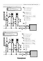
2 ARES Tec connected in a set, managed by an external TGC cascade
regulator.
For any other system applications not included in the
instructions handbook, contact the after-sales service.
* Consult the TGC manual included.
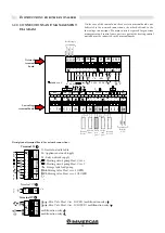
GENERAL
ELECTRICAL
CONTROL
PANEL
GENERAL
ELECTRICAL
CONTROL PANEL
Terminal
board on the
boiler panel
KF boiler
probe
External
probe
Terminal
board on the
boiler panel
External Cascade
Manager
Pos. 2
Pos. 2
Pos. 0
Pos. 0
POS. I
POS. I
Flow switch
Gas
electrovalve
Gas
electrovalve
Flow switch
Boiler supp.
Interface board
IF-EXT.MIN 0-10V
Interface board
IF-EXT.MIN 0-10V
INAIL SECTION
INAIL SECTION
Min pressure switch
Max pressure switch
Thermostat
Boiler supp.
RELAY
RELAY
RELAY
RELAY
Min pressure switch
Max pressure switch
Thermostat
BUS ID HS = 02
BUS ID HS = 01
BUS ID HS = 01
BUS ID HS = 02
BUS ID HS = _ _ _ _


