29
GCI
TGC
GCI
TGC
Instructions for the installer
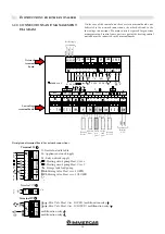
3.18 CONNECTION DIAGRAM
POWER SUPPLY, GAS ELECTROVALVE,
ON/OFF PUMP, EXTERNAL PROBE, FLOW
SWITCH.
POWER SUPPLY, GAS ELECTROVALVE, MODULATING
PUMP, EXTERNAL PROBE, FLOW SWITCH.
If the safety devices are
triggered, the ON/OFF pump
continues operating to lower
the high temperature.
If the safety devices
a r e t r i g g e r e d , t h e
MODULATING pump is
placed on the minimum
sp eed and continues
operating to lower the high
temperature.
NOT
SUPPLIED
NOT
SUPPLIED
GENERAL
ELECTRICAL
CONTROL PANEL
GENERAL
ELECTRICAL
CONTROL
PANEL
Terminal
board on the
boiler panel
Terminal
board on the
boiler panel
Flow switch
Flow switch
Boiler supp. 230 V - 50Hz
External
Probe
External
Probe
Interface board IF-EXT. MIN 0-10V
Press. min
Press. min
RELAY
Thermostat
Thermostat
Press. max
Press. max
Terminal
board on the
boiler panel
ON/OFF pump
Boiler supp. 230 V - 50Hz
Terminal
board on the
boiler panel

