8
MIX 120
Used oil is classified as special waste and must be
treated as such.
Dispose of old oil as
required by law.
Always ensure
that the protection
devices are undamaged
and efficient.
Check
the
condition of the power
cable before starting a
work session; it may
have
become
accidentally damaged.
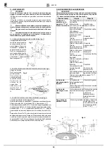
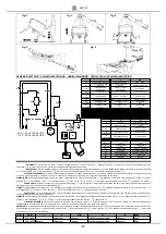
11.1 LIMIT SWITCH
ADJUSTMENT (Fig. 7)
The adjustment of the limit
switch must be carried out with the tank protection cover lowered.
Slacken screw
Ref. 1, line up the
mark on the cam
Ref. 2 with the
limit switch roller
Ref. 3 and tighten
screw Ref. 1. Use
Allen key N° 5.
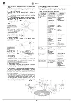
11.2 OUTLET
PROTECTION
REMOVAL (Fig. 8)
Slacken screws Ref. 2 and remove protection Ref. 1. To replace the
protection, align the holes with those of brackets Ref. 3 and tighten
with screws Ref. 2. Use spanner N° 13.
11.3 MIXING PADDLE REPLACEMENT (Fig. 9)
Lift the drum protection cover Ref. 1.
Remove head protection Ref. 2, rotating it in an anti clockwise
direction. Slacken screws Ref. 3 and nuts Ref. 4. Use spanner
N°17.
Remove the paddle clamps Ref. 5, 6 and 7 and replace rubbers Ref.
8, 9 and 10, inserting them between holders Ref. 11, 12 and 13 and
clamps Ref. 5, 6 and 7. Utilize the slots in the rubbers to adjust as
necessary and fix with screws and nuts Ref. 3 and 4.
Push arm Ref. 14 to manually rotate the paddles, checking the mating
of the rubbers with the drum.
If there are zones where the rubber is not in contact with the tank, repeat the adjustment.
Re adjust at positions Ref. 15 and 16 if necessary. Replace and lock in position
protection Ref. 2, rotating it in a clockwise direction. Lower protection cover Ref. 1.
GB
12. TROUBLESHOOTING
WARNING!
All maintenance work must be carried out after the machine
has been stopped, placing the selector switch in the “0”
position and unplugging it.
PROBLEM
CAUSE
REMEDY
The motor does
not run when the
switch is moved to
the"1" position.
- No power in the
supply cable.
- The electric plug
and socket are not
connected properly.
- The cable from the
plug to the electric
panel is broken.
- A wire has
becone
disconnected
inside the panel.
- A wire has
become
disconnected on
the motor terminal
board.
- The switch is
faulty.
- A fuse has blown
inside the panel.
- The protection
cover is open.
- The limit switch is
faulty.
- The cam is
incorrectly
mounted.
- Check the cable.
- Make a proper
connection.
- Replace the cable
- Re make the
connection.
- Re make the
connection.
- Replace the
switch.
- Change the fuse
- Close it.
- Replace it
- Refer to limit
switch adjustment
"11.1".
The discharge
outlet leaks water.
- The sealing
gasket is worn.
- The spring is
broken or
ineffective.
- Replace the
rubber.
- Replace the
spring.
Scraper rubbers
do not mate with
the tank.
- Worn rubbers.
- Replace the
rubbers and/or
adjust their position
(see Mixing Paddle
Replacement
"11.3").
The outlet will not
open.
- Deposits in the
outlet protector.
- Remove and clean
the outlet protector
(see Outlet
Protection
Removal, "11.2").
Fig. 7
Fig. 8
Fig. 9

