⑦
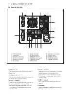
GL IN connector
Inputs the SYNC signal when the camera is to be
genlocked with an external system (internal termination
ȍ,'79YDOXH6\QFRU6'79%%6LV
possible.
,QSXW'799SSG%ȍRU6'79
9SSG%ȍ
⑧
DC IN connector
Used to supply DC power. Input voltage range is shown
below.
When a lens requiring high power consumption is mounted
on the camera head, the camera may not normally operate
if the minimum voltage shown below is underrun. Input a
higher voltage in such a case (+16V or lower).
■
'&9WR9ZKHQWKHFDPHUDFDEOHLVPRU
shorter)
■
DC +12V to +16V (when the camera cable is 30m or
shorter)
No.
Function
①
GND
②
NC
③
NC
④
DC+
5HF$5$3
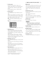
⑨
AWB/ABB indicator
/LJKWVLQJUHHQGXULQJH[HFXWLRQRI$:%$XWR:KLWH
%DODQFHRUOLJKWVLQRUDQJHGXULQJH[HFXWLRQRI$%%
$XWR%ODFN%DODQFH*RHVRXWXSRQFRPSOHWLRQRI$:%
$%%H[HFXWLRQ
%OLQNVZKHQ$:%RU$%%LVLQFRPSOHWH,IEOLQNLQJ
RSHUDWHWKH$:%$%%VHOHFWVZLWFKDJDLQWRFDQFHOWKH
EOLQNLQJVWDWH5HPRYHWKHFRQGLWLRQIRULQFRPSOHWH$:%
$%%DQGUHH[HFXWH$:%$%%
⑩
AWB/ABB select switch
([HFXWHV$:%$XWR:KLWH%DODQFHRU$%%$XWR%ODFN
Balance).
This is a momentary switch, which returns to the midpoint
when released.
When a remote controller is connected to the REMOTE
connector, the operation right goes to the remote controller
and this switch is not operable.
⑪
GAIN select switch
Changes the camera gain. Desired gain values can be set
through camera menus to satisfy L < M < H.
When a remote controller is connected to the REMOTE
connector, the operation right goes to the remote controller
and this switch is not operable.
Set arbitrary gain values in camera menu “MENU
3$*(´!³/2:0,'+,*+*$,102'(´
⑫
MENU switch
When this switch is held down for one second or more, the
menu screen is superimposed on the video signal output
from the MONITOR OUT connector. Turn this rotary
encoder to select a menu, and press it to determine the
menu.
⑬
CAM/BAR select switch
Switches between the video taken with the camera and the
color bar signal.
&$09LGHRWDNHQZLWKWKHFDPHUD
%$5 &RORUEDU
When a remote controller is connected to the REMOTE
connector, the operation right goes to the remote controller
and this switch is not operable.
⑭
POWER switch
Turns ON/OFF the power of the camera.
When turning on the power immediately after
power-off, do so after two seconds or more to
completely discharge the internal electric charge.
⑮
POWER indicator
Lights in green while the power of the camera is ON.
⑯
WARNING indicator
Lights when the input voltage is low. Blinks in red when
an error occurs in the camera or the cooling fan of the
CCU stops. For further details of errors, refer to “MENU
3$*(´!³:$51,1*´
⑰
CAMERA connector
Used to connect the camera cable to the camera head.
3-3
3. NAME and FUNCTION of EACH PART
Содержание HDL-F3000
Страница 1: ...3MOS HDTV CAMERA HDL F3000 Operation Manual Products conforming to RoHS directive ...
Страница 2: ......
Страница 10: ......
Страница 12: ...OCP 100 OCP 100 1209 VOL1 J ...
Страница 14: ......
Страница 20: ......
Страница 64: ......
Страница 66: ......
Страница 68: ......
Страница 69: ......

