background image

112

HC-HD300 1412 VER1 (U)

6.4  Cleaning Camera Connectors

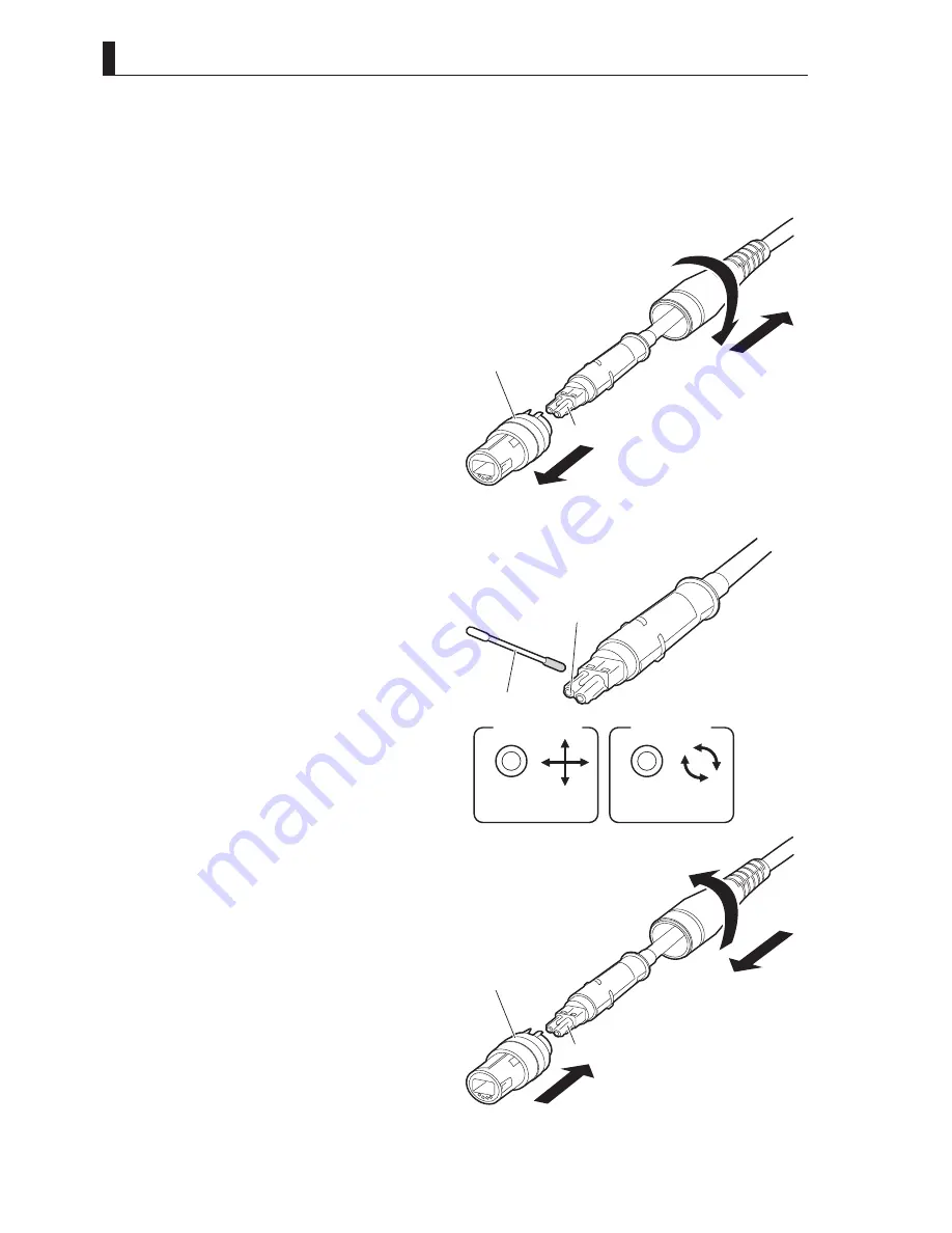
Cleaning the plug (male)

Clean the four sections: receptacle (female) on the camera head, receptacle (female) on the BS, and plugs (male) on both ends of the 

fiber cable.
The following explains how to clean Ferrules using a Neutrik-opticalCON fiber cable plug (male) as an example.

1


 Pull the bushing in the direction of arrow 

, and 

simultaneously pull the connector housing (cable 
side) while turning it in the direction of arrow 

 to 

remove the connector housing.

2


 Wipe the Ferrule with a cotton swab dampened 
with alcohol.

CAUTION:

-  When you wipe the Ferrule, move the cotton swab 

straight in a way in which you brush the dust off the 

Ferrule. Do not wipe back and forth or in a circle. 

Doing so may spread the dirt instead of removing it.

- Do not carelessly blow your breath on the Ferrule.

3


 After wiping the Ferrule with alcohol, wipe the 
Ferrule with a dry cotton swab.

4


Make sure that the dirt is removed.

Use a loupe to examine the Ferrule.

5


 Make sure the ferrule is clean. Then, fit the 
connector housing (terminal side) and the cable 
guide. Insert the connector housing (cable side) 
while turning it in the direction of arrow 

.

Bushing

Connector housing
(Cable side)

Connector housing
(Terminal side)

Ferrule

Good example

Cross section 

of Ferrule

Bad example

Cross section 

of Ferrule

Ferrule

Cotton swab

Bushing

Connector housing
(Cable side)

Connector housing
(Terminal side)

Ferrule

Содержание HC-HD300

Страница 1: ...HIGH DEFINITION CAMERA SYSTEM HC HD300 FA 300 OPERATION MANUAL...

Страница 2: ......

Страница 3: ...NAME and FUNCTION INSTALLATION and 3 CONNECTION 4 OPERATION CAMERA SETTINGS and 5 ADJUSTMENT TROUBLE SHOOTING and 6 MAINTENANCE 7 SPECIFICATIONS CHANGING INFORMATION HC HD300 FA 300 HIGH DEFINITION C...

Страница 4: ...mi Tsushinki Co Ltd We reserve the copyright on the software we create No part of this publication may be modified or reproduced in any form or by any means without prior written permission from Ikega...

Страница 5: ...nt lamps for special purposes 4 Mercury in other lamps not specifically mentioned in this Annex 5 Lead in the glass of cathode ray tubes electronic components and fluorescent tubes 6 Lead as an alloyi...

Страница 6: ...point of lead free solder used for the products conforming to RoHS directive is 20 to 45 degrees Celsius higher than that of conventional solder with lead Sn Pb eutectic solder a high temperature nee...

Страница 7: ...interference to radio communications Operation of this equipment in a residential area is likely to cause harmful interference in which case the user will be required to correct the interference at hi...

Страница 8: ...serious injury or death Indicates that mishandling of the product by ignoring this label may lead to a danger resulting in an injury or property damage The following symbols are used to indicate the e...

Страница 9: ...an AC plug of the BS CCU side Regarding the Product Do not lift or hold the camera by the projection parts If you lift or hold the camera by the viewfinder or the lens you are prone to dropping it Mo...

Страница 10: ...areful not to let a laser beam become directed into the lens of the camera Excessive sound pressure from the headset may cause a hearing loss Regarding the Power and the Lithium Battery Use the produc...

Страница 11: ...where the cable is connected do not drag the cable without winding Turn off the power before removing the fiber optic cable The allowable radius of curvature of fiber optic cables is approximately si...

Страница 12: ...er for safety and for protection against malfunction Clean the product using a dry and soft cloth If the stain is hard soak the cloth with water or detergent wring well and wipe If you use detergent w...

Страница 13: ...lated information is available Term Explains the meaning of a term you need to know Notations The following notations are used in this manual This product camera Indicates HC HD300 Including FA 300 BS...

Страница 14: ...ens and viewfinder Taking examples of studio shooting stand alone shooting and VTR location shooting explains how to connect this product to the peripheral equipment Chapter 4 OPERATION Explains setup...

Страница 15: ...l Operating Systems 33 3 2 Camera and Peripheral Installation and Connection 41 Mounting Removing the Camera on from the Tripod 41 Mounting and Removing the Lens 43 Mounting and Removing the Viewfinde...

Страница 16: ...he OCP or MCP Flashes ON and OFF 107 6 2 TEMP or FAN Appears on the VF Screen 108 6 3 Initializing the Settings of this Product 109 6 4 Cleaning Camera Connectors 111 6 5 Reset the Breaker 114 6 6 Sen...

Страница 17: ...1 OUTLINE...

Страница 18: ...2 HC HD300 1412 VER1 U...

Страница 19: ...little noise even in the stand alone VTR shooting Wideband Digital DTL Includes an advanced digital DTL circuit to improve reproduction including texture and sheen Furthermore improves richer reproduc...

Страница 20: ...es full signal interface with the base station with flexible cabling configuration Equipped with Various Interfaces The camera includes HD SDI signal output The camera has an interface for return vide...

Страница 21: ...S 1 CSU OCP PM WFM PM WFM COMM BS 8 PM WFM COMM WFM COMM PM WFM CONT BS 1 BS 8 IN OUT PM WFM PM WFM WFM CONT COMM MCP Note For Minimum operating System no MCP is needed when the OCP 10 is used When an...

Страница 22: ...on Minimum Configuration of Camera VTR and PM Camera Head BS 1 BS 8 BS 9 BS 16 BS 17 BS 24 BS 25 BS 32 CSU 4 CSU 3 CSU 2 CSU 1 OCP PM WFM PM WFM PM WFM PM WFM PM WFM MCP PM WFM COMM BS 1 BS 8 BS 9 BS...

Страница 23: ...tion cable PoE enabled network hub BSH 300 type C RJ 45 BS CCU MCP Ethernet cable Ethernet cable OCP 10 OCP 100 CP cable MCP cable Term BSH Base Station Hub It is designed as the HUB unit which employ...

Страница 24: ...8 HC HD300 1412 VER1 U...

Страница 25: ...P 170 Note 2 OCP 10 Note 3 MIC 1 Single Mode Fiber Cable Max 10km PM WFM Coaxial Cable AC AC BSH 300 Type C AC MIC 2 Camera Carrying Case Soft Carrying Case Case Cover Dust Proof Cover Rain Proof Cove...

Страница 26: ......

Страница 27: ...2 NAME and FUNCTION...

Страница 28: ...12 HC HD300 1412 VER1 U...

Страница 29: ...itch ND FILTER switch CC FILTER switch ECC Handle RET 2 MIC button RET 1 button Shoulder belt hook Viewfinder VF Switch control panel cover INCOM MIC button Shoulder pad POWER indicator FILTER local i...

Страница 30: ...to the camera Green LED Indicates power is on POWER switch Turns ON OFF the power of the camera or switches the power supply BS Supplies power from the BS to the camera via fiber cable OFF Turns powe...

Страница 31: ...CC FILTER switch ECC and ND FILTER switch CC FILTER switch ECC Selects the ECC filter from the camera A 3200K B 4300K C 6300K D 8000K ND FILTER switch Selects the ND filter from the camera 1 100 2 25...

Страница 32: ...shot by the camera to the viewfinder or monitor BARS Outputs the color bar signal to the viewfinder or monitor 21 GAIN SELECT switch Selects the gain of the camera O Normally selected 0dB value M Gai...

Страница 33: ...1 Camera and Viewfinder Camera Left View VF connector VF CONNECTOR LOCK button CAMERA CABLE clamp Shoulder belt hook RET 1 button Memory Card Slot Breaker CAMERA connector MIC CABLE clamp VF CABLE cl...

Страница 34: ...for the camera MIC CABLE clamp Secures the microphone cable CAMERA connector Connects the camera and BS with a fiber cable It is compatible with NEUTRIK Optical CON DUO connector CAMERA CABLE clamp Se...

Страница 35: ...TION 19 HC HD300 1412 VER1 U 2 1 Camera and Viewfinder Camera Front View LENS LOCK lever Lens mount Cable clamp VF CHAR button ROTARY PULSE switch MIC button P FUNC switch LENS connector SET button 2...

Страница 36: ...appear or disappear P FUNC switch Turns ON OFF the functions allocated by the user The user can allocate the following functions IRIS CORR IRIS CORR AUTO KNEE SKIN DTL SOFT DTL and SCENE FILE ON Turn...

Страница 37: ...OUT connector REMOTE connector DC IN connector AUX OUT connector MIC 2 connector MON SDI connector GREEN TALLY indicator RET 2 SELECT switch RET 1 SELECT switch INCOM 1 MIC switch INCOM 1 control kno...

Страница 38: ...M 2 headset volume The INCOM 1 headset volume is controlled by the controls on the rear of the camera INCOM 2 control knob Controls the intercom volume of the channels allocated to the connector INCOM...

Страница 39: ...mic receiver 22 Q TV GL MON OUT connector Outputs the signal selected by the Q TV GL MON OUT SELECT switch When set to Q TV GL Select the Q TV and VBS signals from the camera menu screen Outputs the...

Страница 40: ...rns ON the intercom microphone while this switch is pressed 30 RET 1 SELECT switch Selects the input connected at the base station as the RET 1 signal sent to the camera 31 RET 2 SELECT switch Selects...

Страница 41: ...View Front View REAR TALLY Lamp with switch Diopter Adjustment lever Escutcheon label display Left View Right View VF cable FRONT TALLY Lamp BRIGHTNESS knob CONTRAST knob PEAKING knob EYEPIECE Release...

Страница 42: ...ewfinder This adjustment has no effect on the output signal of the camera BRIGHTNESS knob Adjusts the brightness of the image in the viewfinder This adjustment has no effect on the output signal of th...

Страница 43: ...n area or safe title area Switching between the action area and the title area is made from the menu The Frame Marker is used to ascertain the frame of the image being shot Aspect ratio 4 3 13 9 14 9...

Страница 44: ...ADJUSTMENT Menu Configuration and content P81 for how to set the side mask Display Mode The display mode sets the markers and characters to be displayed in the viewfinder Reference The display mode i...

Страница 45: ...412 VER1 U 2 2 Displays in the Viewfinder Warning Display Auto Setup Display Return Video Channel Display Temperature warning Auto setup function Execution result of auto setup Adjustment item of auto...

Страница 46: ...en the fan has stopped abnormally AWB color temperature The color temperature stored in A ch or B ch memory is displayed for 2 seconds when the AWB ABB switch is operated Selection between A ch and B...

Страница 47: ...3 INSTALLATION and CONNECTION...

Страница 48: ...32 HC HD300 1412 VER1 U...

Страница 49: ...pheral equipment such as the BS Camera right view BS front view POWER switch MAIN POWER switch Connection Examples for Typical Operating Systems Not only can the HC HD300 be used stand alone for video...

Страница 50: ...34 HC HD300 1412 VER1 U...

Страница 51: ...OCP 10 Note 4 CP Cable Max 300m Note 3 AC ADAPTER AC HC HD300 FA 300 Note 1 Only applicable for the self contained system operation Note 2 Selection between Q TV GL and MON OUT is made by the switch...

Страница 52: ......

Страница 53: ...Headset PROD FA 300 Camera rear Headsets 12Pin Zoom Lens Tripod Tripod Mount Plate Coaxial Cable Coaxial Cable Zoom Remote Control Box Fiber Cable MAX 350m with VFL200HD MAX 250m with VFL P700 NTSC H...

Страница 54: ......

Страница 55: ...Note 1 DC Power Cable DC 11 to 16V Single Mode Fiber Cable Max 10km Hybrid Fiber Cable Case 1 Hybrid Fiber Cable connection Case 2 Single Mode Fiber Cable connection local power BSF 300 Base Station...

Страница 56: ......

Страница 57: ...end the tripod legs Adjust the height of the tripod to the desired height 2 Tighten the lock knobs to lock the tripod legs 3 Make sure that the tilt lock and pan lock are locked If they are not locked...

Страница 58: ...ke to a low number will minimize friction and ensure smooth movement 8 After positioning the camera to the desired pan and tilt tighten the tilt lock and pan lock to lock the camera Removing the Camer...

Страница 59: ...nsert the lens into the camera lens mount Support the lens with your hand to prevent it from falling 3 Secure the lens to the camera Push down the lens lock lever to secure the lens to the camera Make...

Страница 60: ...and release it from the lens connector 2 Remove the lens from the camera Rotate the lens lock lever Counter clockwise to the end stop and remove the lens from the camera horizontally Support the lens...

Страница 61: ...t of the camera from the left hand side Slide the viewfinder until it clicks into position When the viewfinder is locked to the camera by the lock pin it clicks 4 Set the VF slide lock CW to lock the...

Страница 62: ...eyepiece can be rotated 160 degrees upward and 90 degrees downward Adjust the eyepiece angle in accordance with the camera angle Removing the Eyepiece This section explains how to remove the eyepiece...

Страница 63: ...der to open it 3 Put the microphone in the opened microphone holder and tighten the screw to secure it in place 4 Connect the microphone cable to the MIC 1 connector on the rear of the camera This ste...

Страница 64: ...or too loud Refer to 5 CAMERA SETTINGS and ADJUSTMENT Adjusting Headset Volume P71 for how to control the intercom volume Attaching the Shoulder Belt Attaching the Shoulder Belt This camera is equippe...

Страница 65: ...o Make Sure the Power Switch is OFF P33 for how to check the power Power Supply from AC Adapter This section explains how to supply the power from an AC Adapter external power For the details on the A...

Страница 66: ...h is OFF 2 Connect the AC cable to the AC INPUT connector on the rear of BSF 300 3 Insert the AC plug into the power outlet 4 Connect the BSF 300 and the camera via a fiber cable This completes the pr...

Страница 67: ...t of the BS to ON This turns on the power of the BS and lights the BS MAIN POWER indicator In addition the status of the camera cable connection between the camera and the BS is automatically checked...

Страница 68: ...ECT switch If Q TV GL is selected this connector outputs the Q TV OUT VBS signal when the camera is connected to the BS or it inputs an external synchronization signal GENLOCK when the camera is used...

Страница 69: ...amera and BS Fiber cable Camera rear view CAMERA connector CAMERA connector BSF 300 rear view 1 Connect the CAMERA connector on the rear of the BSF 300 to the CAMERA connector on the rear of the camer...

Страница 70: ...mage the fiber in the cable Camera Camera rear view CAMERA connector Fiber cable Unlocking ring Plug BS Plug BSF 300 rear view Fiber cable CAMERA connector 1 Remove the cable while pulling the unlocki...

Страница 71: ...4 OPERATION...

Страница 72: ...56 HC HD300 1412 VER1 U...

Страница 73: ...paration Before Shooting 4 4 Viewfinder Adjustment P62 Diopter Adjustment and Screen Adjustment Display Mode Check 4 5 Output Signal Check P63 Color Bar Signal Check Test Pulse Check CAL Signal Check...

Страница 74: ...Pressing the FILTER HEAD switch will switch the operational priority between the camera and the BS Camera Front P FUNC switch OFF Note When the camera is connected to the BS you cannot use the P FUNC...

Страница 75: ...le SW1 OFF Default function is ZEBRA Assignable SW2 OFF Default function is TALLY Assignable SW3 OFF Default function is MONO Note You can change Function SW assignment with the MENU of the VF FRONT T...

Страница 76: ...n the camera to EXT Power will be supplied to the camera and the POWER indicator will light in green Power Supply from BS Before turning the camera ON set the switches to the following positions in no...

Страница 77: ...icator Note You can display the self diagnosis information and check the status on the PM attached to the base station by pressing the PM IND PAGE button even when the ALARM indicator is not flashing...

Страница 78: ...e in the direction of the arrow Screen Adjustment Adjust when the viewfinder image is not clearly viewable or if you want to enhance the edge of the image 1 Adjust the knobs on the viewfinder PEAKING...

Страница 79: ...CONNECTION P31 for connection of peripheral equipment Color Bar Signal Check 1 Set the BARS button on the OCP or MCP to ON Ensure that a normal color bar signal is output To output color bar signals...

Страница 80: ...ton on the OCP or MCP to ON Ensure that 100 level of test pulse is output Note If an OCP 10 is used make sure you assign the CAL function to an F switch for this check 100 80 60 40 20 0 20 MCP OCP PM...

Страница 81: ...vated from the camera OCP and MCP See the table in the next page for which device can activate which auto setup function Reference For how to execute auto setup from the OCP MCP refer to the relevant...

Страница 82: ...D switch to switch the operational priority to the camera When the priority is given to the camera an asterisk is displayed in the viewfinder 3 Shoot a subject which contains something white Make sure...

Страница 83: ...of auto black balance OK or NG appears on the viewfinder screen CAUTION Be sure to set the R G B BLACK and MASTER PEDESTAL control knobs on the OCP to the center position before activating the auto b...

Страница 84: ...herwise the oil freezes because of the extremely low temperature and the movement of the tripod focus zoom and iris will become heavy Put a cold weather cover on the camera and fully warm up the camer...

Страница 85: ...5 CAMERA SETTINGS and ADJUSTMENT...

Страница 86: ...70 HC HD300 1412 VER1 U...

Страница 87: ...view Camera rear view INCOM FRONT VR SELECT switch INCOM 1 MIC switch INCOM 2 MIC switch INCOM 1 control knob INCOM 1 PGM control knob INCOM 2 control knob INCOM 2 PGM control knob INCOM PHONE contro...

Страница 88: ...1 2000 Variable shutter Set the suitable shutter speed within the following range 1 60 2 to 1 2040 seconds scanning mode 59 94Hz 1 50 2 to 1 2000 seconds scanning mode 50Hz Variable Shutter function i...

Страница 89: ...and SUPER V 3 Select PRESET SHUTTER SPEED or VARIABLE SHUTTER SPEED 4 While the characters are flashing in the viewfinder turn the rotary pulse switch to the appropriate shutter speed and press the S...

Страница 90: ...e switch 1 Select 1 or 2 from MENU 1 4 VF DISPLAY DISPLAY MODE Characters appear in the viewfinder Reference Refer to 5 2 Settings from the Menu Menu Configuration and content P81 for details 2 Set th...

Страница 91: ...t side of the camera to switch the setting according to the shooting conditions Note Allocate gain values to the GAIN SELECT switch in advance Refer to 5 2 Settings from the Menu Menu Configuration an...

Страница 92: ...the P FUNC switch Selection Display Function SKIN DTL Turns ON OFF the SKIN DTL function IRIS CORR Turns ON OFF the mode to adjust the iris by approximately 1 2 STOP when AUTO IRIS is set IRIS CORR Tu...

Страница 93: ...n unnatural appearance The Soft DTL function acts as a limiter on the maximum white and black edge from the detail system and can be used to prevent harsh edges There are two ways to activate the skin...

Страница 94: ...viewfinder or the monitor Camera front view VF CHAR button SET button Rotary pulse switch Rotary pulse switch Used to select a setting item SET button Pressed to confirm the selection and setting VF...

Страница 95: ...on the submenu that is displayed from the main menu in the viewfinder or monitor 1 Make sure that the main menu is displayed 2 Turn the rotary pulse switch on the front of the camera to position the c...

Страница 96: ...1 U 5 2 Settings from the Menu Exiting the Menu This section explains how to exit the main menu submenu in the viewfinder or monitor 1 Press the VF CHAR button on the front of the camera The main menu...

Страница 97: ...using the serial lens AUTO VF ASPECT OFF ON OFF Switches the VF aspect ratio in linked motion with the output mode of the BS CCU down converter Overlaps the striped pattern signal on the image if the...

Страница 98: ...AREA MARKER OFF ON OFF Sets whether the assist area frame marker is displayed or not EDGE BOOST LEVEL 55 0 to 100 Sets the boost level of the edge signal EDGE COLOR MONO MONO CYAN MAGENTA YELLOW GREEN...

Страница 99: ...display Displays the total accumulated operation time of the camera up to the present SUB TIME H information display RESET Displays the camera s calculated operation time Differs from WORKING TIME be...

Страница 100: ...d to display warning BARS MODE BARS MODE Destination setting FULL MULTI FULL Displays the BARS signal conventionally used MULTI Displays the multiformat BARS signal BARS ON OFF ON OFF Turns the color...

Страница 101: ...ry card SNAP SHOT SCENE REFERENCE LENS MENU DATA LOAD FILE ALL DATA Loads all files SNAP SHOT Loads snapshot files SCENE ALL SELECT NUMBER Possible to select whether to load all from SCENE DATA or to...

Страница 102: ...ion IRIS GAIN 50 1 to 100 Sets the auto iris response sensitivity characteristics The auto iris operation sensitivity is such that 1 is low and 100 is high Hunting tends to occur more often as the val...

Страница 103: ...ching X0 8 CONV CONT OFF ON OFF If turned ON when using the X0 8 converter internal lens control is possible When not using the X0 8 converter internal lens set to OFF LENS SERIAL I F ON ON OFF Set wh...

Страница 104: ...age with less noise PRESET FILE LOAD Function to load the user settings ENGINEER SET FILE or factory settings FACTORY SET FILE for the level adjustment or menu of the camera Used to return the camera...

Страница 105: ...H LEFT RIGHT Do the Assignment Settings to the head set of PGM2 channel INCOM2 L R CH INCOM1 BOTH BOTH LEFT RIGHT Do the Assignment Settings to the head set of INCOM1 channel INCOM2 BOTH BOTH LEFT RIG...

Страница 106: ...ed In this case stops power supply from an optical cable SINGLE MODE OFF ON OFF If it is sets to ON the mode is switched to the single fiber mode CAMERA ID SETUP PROGRAM NO 1 1 to 99 OFF You can set t...

Страница 107: ...ICOM2 is set to CARBON INCOM2 GAIN NORMAL NORMAL HI Sets the GAIN of the dynamic microphone when CARBON is selected in ICOM2 RECEIVE INCOM1 L R CH INCOM1 BOTH BOTH LEFT RIGHT Sets the assignment of I...

Страница 108: ...of INCOM1 to INCOM2 INCOM1 INCOM2 OFF ON OFF Connects TALK line of INCOM2 to INCOM1 DATA SAVE READY READY USER1 USER2 CANCEL Saves data as USER1 or USER2 PGM FRONT VR PGM1 PGM1 PGM2 Selects the signa...

Страница 109: ...nnected HD SDI OUT COLOR FILTER LPF4 LPF1 LPF2 LPF3 LPF4 Sets the frequency band of color difference signal P b P r for HD SDI signal The LPF1 is narrow band and LPF2 and LPF3 are wider bands in the r...

Страница 110: ...e creation of lens file requires precise adjustment therefore lens files are protected against unintentional update by the S3 4 DIP switch of the MPU module When creating a lens file set the optical f...

Страница 111: ...tom of the screen LENS No x Displayed when MANUAL is selected PUSH SET START Displayed and flashes when AUTO is selected Go to Step 7 when AUTO is selected When MANUAL is selected go to Step M1 to obt...

Страница 112: ...COMPLETED disappears a newly loaded model name will appear Note BB40X10 BCDE is used here for an example of the model name automatically and newly obtained from the lens M3 Turn the rotary pulse swit...

Страница 113: ...an be shared with a similar lens The following explains the procedures E1 Follow Steps 1 to 3 of lens file creation to display the submenu E2 Turn the rotary pulse switch to position the cursor on NUM...

Страница 114: ...for performing AUTO READ E7 Turn the rotary pulse switch to switch the cursor from CANCEL to EDIT and press the SET button The under submenu AUTO SEL NAME EDIT is displayed E8 Turn the rotary pulse sw...

Страница 115: ...firm The edit mode is terminated and at both ends stop flashing Now go to Step M3 CAUTION 1 The processing for AUTO READ is as follows When a serial lens is connected The model name of the serial lens...

Страница 116: ...operation Inserting and removing the memory card There is a memory card slot as shown in the illustration below on the bottom left side of the camera main unit Open the dustproof cover and insert the...

Страница 117: ...ng the item you wish to save press the SET button Then use the rotary pulse switch and SET button to insert an eight character file name When the eight character file name has been determined PUSH SET...

Страница 118: ...te over the data To enable writing over of data change NO to YES and press the SET button If NO has been selected storage is cancelled and the system returns to step 3 Note The images of the storage r...

Страница 119: ...the SET button If you wish to cancel turn the rotary pulse switch when PUSH SET START is displayed Note SCENE FILE LENS FILE MENU DATA is about it is possible to select individual data ALL or all data...

Страница 120: ...he error messages and contents are as shown below Error Message Contents NO CARD Memory card not inserted CANNOT OPEN FILE File cannot be opened NOT CAMERA DATA FILE Not a camera data file FILE OF DIF...

Страница 121: ...6 TROUBLE SHOOTING and MAINTENANCE...

Страница 122: ...106 HC HD300 1412 VER1 U...

Страница 123: ...S and camera are running normal As soon as the BS main power switch is turned ON the self diagnostic function starts running and always runs during operation If the BS or camera becomes abnormal the d...

Страница 124: ...on the camera to avoid direct sunlight The camera is used near some heating appliance Move the position of the camera or heating appliance If a fan stops due to some failure a warning indicating an i...

Страница 125: ...T ENGINEER default Initializes the state back to the user setting FACTORY Initializes the state back to the initial factory setting LOAD START READY default The state before initialization START Start...

Страница 126: ...reen Go to Step 6 when selecting START 6 Press the SET button Initialization starts When the file load is completed COMPLETED appears on the screen Then CAMERA RESTART blinks for about three seconds A...

Страница 127: ...attenuation occurs If Ferrules are extremely dirty optical signals are interrupted and the fiber cable may not work properly Regular cleaning of Ferrules is suggested if the camera connector is freque...

Страница 128: ...e cotton swab straight in a way in which you brush the dust off the Ferrule Do not wipe back and forth or in a circle Doing so may spread the dirt instead of removing it Do not carelessly blow your br...

Страница 129: ...eaning method of a female pin CAUTION When you clean a female pin use NEUTRIK cleaner FOCD DC125 1 Remove the cap of cleaner and push the insert of pin to open the shutter 2 Insert the cleaner until y...

Страница 130: ...ied to the camera even though the power is on and peripherals are connected correctly it might mean that the power has been cut off by the breaker In this case reset the breaker as follows 1 Check tha...

Страница 131: ...e for small defective pixel singular pixel The defective pixel correction is performed every time that auto black balance is performed The auto black balance can be performed from camera and from OCP...

Страница 132: ...116 HC HD300 1412 VER1 U...

Страница 133: ...7 SPECIFICATIONS...

Страница 134: ...118 HC HD300 1412 VER1 U...

Страница 135: ...12 Ambient temperature Operation temperature 20 to 45 Storage temperature 30 to 60 13 Ambient humidity 30 to 90 No condensation 14 EMI FCC Class A 15 External dimensions Approx W138 5 H270 D337 Not i...

Страница 136: ...D ENG Input signals FA 300 Item Rating Remarks 1 Return video signal None 2 External SYNC signal SYNC 0 6Vp p 6dB BB PS signal 3 Audio signal 60 to 4dB variable 20dB fixed 600 balance 2 channels 4 Int...

Страница 137: ...121 HC HD300 1412 VER1 U 7 2 External Dimensions Diagram 7 SPECIFICATIONS 7 2 External Dimensions Diagram Right View 337 5 7 2 1 270 5...

Страница 138: ...122 HC HD300 1412 VER1 U 7 2 External Dimensions Diagram Left View 94 3 7 1 337 5 270 5...

Страница 139: ...123 HC HD300 1412 VER1 U 7 2 External Dimensions Diagram 7 SPECIFICATIONS Front View 138 5 3 94 3 7 1...

Страница 140: ...124 HC HD300 1412 VER1 U 7 2 External Dimensions Diagram Rear View 138 5 3...

Страница 141: ...1 V 0 5 V VTR TRIG VTR START STOP signal VTR START 0 5 V or less Zout 10 M or more VTR STOP OPEN Zout 1 5 k or less Zin 100 k 5 10 k or more Momentary action IN 2 V 0 5 V GND D N G s n e l r o f d n...

Страница 142: ...k 5 100k or more IN OUT 9 V 0 5 V ZOOM FOLLOW Lens zoom control output WIDE 2 0 V 0 05 V 2 0 V 0 2 V TELE 7 0 V 0 05 V 7 0 V 0 2 V Zin 100 k 2 10 k or more Zout 1 k 10 1 k or less IN FOCUS FOLLOW Len...

Страница 143: ...Y G 6 7 75 G Y VF VIDEO RET Ground for G Y VF VIDEO output signal RET VF M CLK Reference clock pulse signal for serial data reproduction OUT SP WR Read pulse signal for serial parallel data conversio...

Страница 144: ...k Camera head side N02 4FDW 1 AS Receptacle B A 4 3 2 1 Pin No Name Function I O External Interface A OPT B H Optical contact BS Camera IN B OPT H B Optical contact Camera BS OUT DC 50V RET RET DATA O...

Страница 145: ...P81 7 pin Type 1 2 3 7 4 5 6 Insertion Side Camera head side NC7FD LX B Neutrik Cable side XLR 7 12C Receptacle e c a f r e t n I l a n r e t x E O I n o i t c n u F e m a N o N n i P LISTEN L C Shie...

Страница 146: ...LD Shield for LISTEN L LISTEN R output GND 4 3 5 LISTEN Lch H LISTEN L output H OUT PGM Rch H PGM R output H OUT Receiver Receiver Intercom microphone 4 pin Type 4 3 2 1 Insertion Side Camera head sid...

Страница 147: ...TALK Input to and output from intercom microphone IN OUT 114B Jack 2 R 3 R S 5 T 4 T S 1 SLV Camera head side 114B SWITCH CRAFT Cable side 110 phone plug e c a f r e t n I l a n r e t x E O I n o i t...

Страница 148: ...t shield MIC HOT MIC HOT line 600 balanced input When AB power is supplied DC 12V When 48 phantom power is supplied DC 48V IN MIC COLD MIC COLD line 600 balanced input When AB power is supplied DC 0V...

Страница 149: ...n u F e m a N o N n i P A HED Digital data output from camera to remote controller OUT B HED Digital data output from camera to remote controller OUT C HEC Digital data output from remote controller...

Страница 150: ...te controller OUT PC TXD Digital data output from camera to remote controller OUT 12 V RET Ground for DC 12V power supply RET 12 V DC 12V power supply to remote controller OUT R TALLY T U O l a n g i...

Страница 151: ...NUAL KNEE ON OFF Adjusted value SMOOTH KNEE OFF TYPE1 to TYPE3 AUTO KNEE ON OFF Adjusted value SUPER KNEE OFF LOW MID HIGH WHITE CLIP ON OFF Adjusted value VARIABLE C TMEP ON OFF Adjusted value ECC FI...

Страница 152: ...136 HC HD300 1412 VER1 U...

Страница 153: ...INFORMATION CHANGING INFORMATION This chapter contains the revision information of user specific specification or design change requested by users or any changes done by Ikegami Read by comparing this...

Страница 154: ...138 HC HD300 1412 VER1 U...

Страница 155: ...of Ikegami Tsushinki Co Ltd December 2014 Ikegami Tsushinki Co Ltd All rights reserved Reproduction or duplication without permission of Ikegami Tsushinki Co Ltd of editorial or pictorial content in...

Страница 156: ......

Страница 157: ......

Страница 158: ...9171 Fax 1 201 569 1626 E Mail engineering ikegami com service ikegami com URL http www ikegami com Ikegami Electronics Europe GmbH Ikegami Strasse 1 D 41460 Neuss GERMANY Phone 49 0 2131 123 0 Fax 4...

Отзывы: