background image

7

Buccaneer GTE - 

Installation & Servicing

GENERAL

3

VENTILATION

The ventilation requirements in the gas fired boiler standard
are also valid for oil fired boilers of the same heat input.

The ventilation requirements of these boilers is dependant on
the type of flue system used, and their heat input.  All vents
must be permanent with no means of closing, and positioned
to avoid accidental obstruction by blocking or flooding.
Detail reference should be made to BS 5440 Pt. 2.  The
following notes are for general guidance only:
If installed in a room or internal space then a permanent air
vent is required.  The sizes for vents directly communicating
with outside air shall have a free area of 5cm

2

 per kW of boiler

rated input in excess of 7kW.
If installed in a compartment, then permanent air vents are
required at high and low level.  These vents may
communicate direct to outside air, or to a room/internal space.
If to room/internal space, it must itself be adequately
ventilated as above.

4

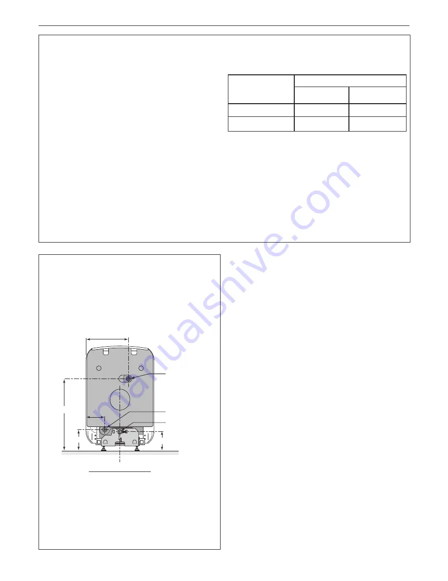
HYDRAULIC CONNECTION

buc5492

355

562

137

Flow
Connection 1

1

/

4

"

Return
Connection 1

1

/

4

"

Drain Cock

120

158

Note

.

Remember that boilers installed in or close to rooms in which
the atmosphere is polluted with chlorine or fluorine compounds
may be subject to high corrosion.
For example: hairdressing salons, industrial premises
(solvents), cooling equipment etc.
Boiler installed in such locations shall not be covered by the
warranty.

Minimum vent free area
(cm

2

) per kW of boiler

rated input positioned at:

Open-flued

To room or

internal space

Direct to

outside air

High Level

Low Level

10

20

5

10

FILLING THE SYSTEM

Filling shall be performed with a low flow rate from a low point
in the boiler room in order to ensure that all the air in the boiler
is bled from the high point of the system.

Always stop the pump before filling.

IMPORTANT. 

 Instructions for starting up the boiler for the first

time after the system is fully or partly drained:

If all the air is not bled naturally to an expansion vessel which
opens out onto the air, the system must include manual
bleeder valves, in addition to automatic bleeder valves with the
capability to bleed the system by themselves when it is
operating.  The manual bleeder valves are used to bleed all
the high points of the system and to make sure that the filled
system is free of air before the burner is turned on.

General

Recommendations relating to the water system are contained
in BS. 5449 and BS. 6880.

Содержание Buccaneer GTE 5

Страница 1: ......

Страница 2: ...formance It is therefore important that no external control devices e g flue dampers economisers etc are directly connected to these appliances unless covered by these Installation and Servicing Instr...

Страница 3: ...tion servicing or cleaning of this appliance care should be taken when handling edges of sheet steel components Buccaneer GTE Gas and Fuel Oil PI No 0049 BM 3528 Destination Countries GB IE INTRODUCTI...

Страница 4: ...ces BS 5449 Forced circulation hot water central heating systems for domestic premises Note only up to 45kW NOTE TO THE INSTALLER LEAVE THESE INSTRUCTIONS ADJACENT TO THE BOILER BS 5482 Pt1 Domestic b...

Страница 5: ...HOT WATER AND HEATING BOILERS There is a basic need to treat the water contained in all heating and indirect water systems particularly open vented systems It is assumed incorrectly that because boil...

Страница 6: ...turn R 1 1 4 3 Drain cock connection for pipe int 14 mm 4 4 x M8 on 110 Insulation Cutout 2 BOILER CLEARANCES The minimum dimensions indicated on the following drawing must be respected to ensure good...

Страница 7: ...lers installed in or close to rooms in which the atmosphere is polluted with chlorine or fluorine compounds may be subject to high corrosion For example hairdressing salons industrial premises solvent...

Страница 8: ...as or water undertakings b The installation should be capable of working with flow temperatures of up to 90o C and a temperature differential of up to 20o C c All components of the system including th...

Страница 9: ...lue Gases kg s Natural Gas 9 CO2 Flue Gas Temperature 1 2 Chimney Minimum Recommended Dimensions kW mbar o C min m m Height m GTE4 21 27 0 12 0 014 0 014 180 125 6 5 GTE5 27 33 0 12 0 017 0 017 190 12...

Страница 10: ...nections to the burner unit MUST comply with the requirements of BS 799 The installation should conform to the recognised standards of good practice in the trade and comply with the relevant Codes of...

Страница 11: ...ns accompanying the options A DHW Sensor Kit AD 212 is available for use with the Buccaneer GTE range 11 BOILER BODY PREPARATION Put a protective piece of cardboard on the floor in front of the boiler...

Страница 12: ...the screw bag making the joint water tight using hemp or sealing paste 5 Put the boiler body back on its feet 13 REVERSE THE DIRECTION OF OPENING OF THE BURNER DOOR IF NECESSARY OPENING AT LEFT 1 2 1...

Страница 13: ...t hand side 3 Remove the 2 screws on the left hand side 4 Reinstall the cast iron hinge pin 2 for the burner door on the left side 15 INSTALLING THE INSULATING MATERIAL 1 Pass the strap between the ca...

Страница 14: ...The assembly rod 3 The rear section positioning pin 4 Fix it at the front with two M8 flanged nuts 5 Fix the rear section with one M8 x 30 screw and flanged nut on one side and one flanged nut on the...

Страница 15: ...16 screws and square nuts 4 Replace the control panel display 5 Fix the top part of the control panel using the black screw for plastic supplied for this purpose 6 Fit the earth wire spade connector...

Страница 16: ...ide panel into place engaging the lower notch of the panel in the cross bar of the base 2 Make sure that the lower fold in the panel is correctly positioned under the fold of the cross bar 3 Straighte...

Страница 17: ...at the back with two 3 94 x 12 7 self tapping screws and 2 serrated washers Note It may be found suitable to make electrical connections before completing the casing assembly If so refer to Frame 33 3...

Страница 18: ...nto contact with the side panels and fix it using two black M6 x 10 screws delivered in the casing screw bag 4 2 1 3 3 4 BUC5513 Black screws 28 FINAL LEVELLING OF THE BOILER Level the boiler by adjus...

Страница 19: ...hermostat Temperature Resistance Thermostat Temperature Resistance Knob setting in o C in ohm Knob setting in o C in ohm 5 50 3 661 1 10 19 691 6 60 2 535 2 20 12 474 7 70 1 794 3 30 8 080 8 80 1 290...

Страница 20: ...on combination mobels Titanium anode optional standard on combination mobels If a titanium anode is not used then the connector supplied in the AD 212 kit with the 22kOhm resistance and a 100nF capaci...

Страница 21: ...er removal of link zone A Room thermostat at terminals 19 and 20 zone B do not fit link if zone B not used Safety contact to terminals 4 and 5 after removing link Remote alarm to indicate overheat low...

Страница 22: ...CUIT A DHW LOAD PUMP HEATING PUMP CIRCUIT B BURNER A B B CS DJ4A FA J L N RL BR RL ECS RL PA RL PB S CH S ECS TA TAM A TAM B TS VA ZG ZEH ZT SAFETY CONTACT CIRCUIT BREAKER ANTI PARASITE FILTER PRINTED...

Страница 23: ...un 1 The potentiometer on the PCB in the boiler is used to adjust the DHW pump overrun The overrun can vary with an adjustment range from 0 to 10 minutes factory setting 4 min Setting the Domestic Hot...

Страница 24: ...panel clear from the clips and the notches in the top part pulling it towards you 4 Remove the front panel from the notches near the bottom of the side panels 5 Unscrew the attachment screw fastening...

Страница 25: ...mittently operating the DHW load pump and the CH pump This air elimination sequence is de activated if the calorifier temperature is more than 250 C Summer Winter Switch If DHW has been in demand a de...

Страница 26: ...RICAL INSTALLATION 1 Checks to ensure electrical safety should be carried out by a competent person 2 ALWAYS carry out the preliminary electrical system checks i e earth continuity polarity resistance...

Страница 27: ...eaning the Casing Material and Control Cover Use a soapy solution and sponge only Rinse with clean water and dry with chamois leather or soft cloth 2 4 3 3 2 1 buc5523 47 CLEANING THE FLUEWAYS 1 Disco...

Страница 28: ...e system hot examine all water connections for soundness Check the gas rate and measure the combustion CO CO2 content Complete the boiler log book Carry out functional checks as appropriate 50 SERVICI...

Страница 29: ...GS Installation commissioning and maintenance must be carried out by a qualified technician in accordance with installation practices and the instructions in this document Regular maintenance of the e...

Страница 30: ...the location of which must comply with local recommendations 61 buc5537 1 4 2 3 355 1011 1181 756 158 285 738 516 286 7 6 5 300 600 C 130 F B 930 160 1306 250 53 82 5 918 4 x M8 on o 150 Burner Plate...

Страница 31: ...leeve in steel cast iron or insulating material must be placed between the hot water outlet of the unit and this pipework so as to avoid any corrosion at the level of the branch pipe Notes The safety...

Страница 32: ...54 YA type pressure change health regulations 56 Return circulation loop 57 Domestic hot water outlet 54 PACKAGING The following table shows the box numbers included with the boiler to be installed B...

Страница 33: ...eet Basic height 35mm adjustment range 35 40mm 19 buc5542 57 ASSEMBLING THE BOILER ON THE HOT WATER CALORIFIER Locate the boiler on top of the hot water calorifier ensuring accuracy of dimension P at...

Страница 34: ...sor in the attachment lug provided for it on the tank inspection plate Make the electrical connection in accordance with the instructions for the control panel 6 Put the thermal insulation into place...

Страница 35: ...ump adapter elbow to the tank return pipe 4 Fit the other adapter elbow to the tank flow pipe 5 Plug or fit drain cocks to the bottom outlets at the tank adaptors 1 Fit the pump to the tank adaptor en...

Страница 36: ...the tank by pressing the boiler start stop button WARNING Top up the primary circuit with water 5 Put the non return valve into the automatic position A 6 Put the automatic air vent back into place 6...

Страница 37: ...the drain position before starting to drain the safety unit and open a hot water tap to allow air to enter Lift up the front panel to remove it Remove the sensor Remove the inspection flange 13mm span...

Страница 38: ...38 Buccaneer GTE Installation Servicing NOTES...

Страница 39: ...39 Buccaneer GTE Installation Servicing NOTES...

Страница 40: ...nuing improvement in the design and performance of its products The right is therefore reserved to vary specification without notice The Ideal Boilers Technical Training Centre offers a series of firs...

Отзывы: