8
Innovative Circuit Technology Ltd.
Figure 2: Installing Power Module in a Hybrid Power Shelf
Install Unit
WARNING
Risk of serious personal injury or damage to equipment and property! Always
observe the following!
•
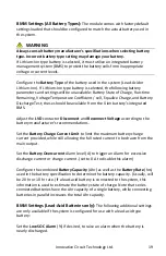
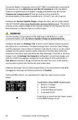
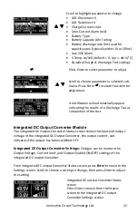
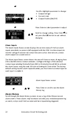
When using a backup battery ensure the nominal battery voltage is correct
for the model of power modules
installed, and that the battery positive is
connected to the positive (+) terminal and the battery negative is
connected to the (-) terminal.
Note that the BAT terminal on the BMM
may be internally tied to the (+) or (-) shelf output through the LVD
contactor, depending on the polarity of the power shelf used (see the
application note of DN-
113v3, “Understanding
-Polarity
”)
•
Use an appropriate DC over-current protection device such as a fuse or
circuit breaker in-line with and near to the battery connection
•
Do not tie either power shelf main output to the BAT terminal on the BMM,
as this may short circuit the battery or bypass the internal LVD circuitry in
the BMM
•
Make any earth ground connection to only a single LOAD or BAT terminal if
required. Do not ground both the load and battery as this may bypass the
internal LVD circuitry
•
AC input wiring to the Hybrid Power Series unit must be protected using an
outlet with a branch rated circuit breaker of 30 A or lower value
Module Latch


