background image


Innovative Circuit Technology Ltd. 

11 

string using the adhesive backed clip, as shown in Figure 5. The rate of 
voltage compensation can be adjusted via the ICM front panel interface, or 
the WEB GUI in the Battery Backup Settings & Control tab. The default 
compensation is 0mV/C per cell (no compensation adjusts this according to 
the battery 

manufacturer’s recommendation 

to enable charge voltage 

temperature compensation. Battery temperature is assumed to be 25° C if 
no sensor is installed. 


Figure 5: Battery Temperature Sensor Installation 


Install wiring to monitor up to four external voltage free alarm contacts, 
typically for external sensors such as a door or window switch, smoke 
detector output, or water detector etc. Enable the alarm inputs and set the 
contact logic (normally open or contact normally closed) in the WEB GUI, 
Alarms Settings & Control tab. 


Pin Number 

Name 

Function 

Alarm 1 

Remote alarm 1 input  

Alarm 2 

Remote alarm 2 input  

Alarm 3 

Remote alarm 3 input  

Alarm 4 

Remote alarm 4 input 

Alarm Return 

Common remote alarm return point 

Bat Temp 

Remote Battery Temperature sensor 

Bat Temp 

Battery temp sensor return 


Remote Input Connector: (use 22-26 AWG wire) 


Make Battery Connections to BMM  

The BMM provides a convenient and safe way to connect an external lead-acid 
or lithium-ion back-up battery to the Hybrid Power Series. A 100 A high current 
hydraulic-magnetic circuit breaker provides over current protection, while an 
internal LVD contactor will disconnect the battery should it discharge below a 
safe level. Internal battery current monitoring provides a full suite of remote 
battery charge monitoring features. 


Содержание Hybrid Power ICT-IPS-DC12-BMM

Страница 1: ...s INSTRUCTION MANUAL 855 350 000 Innovative Circuit Technology Ltd Models ICT IPS DC12 BMM ICT IPS DC12 BMMP ICT IPS DC12 BMMD ICT IPS DC12 BMMDP ICT IPS DC24 BMM ICT IPS DC24 BMMP ICT IPS DC24 BMMD I...

Страница 2: ...current levels Use an appropriate DC over current protection device in line with the back up battery connection Use a disconnect switch or circuit breaker in series with the battery connection to ensu...

Страница 3: ...s 21 Alarm History 22 Network Status and Advanced Options 23 Password Reset Front panel 24 OPERATION No ICM 24 OPERATION Network GUI 24 Log In to the Unit 24 System 25 Power Modules 26 Battery Backup...

Страница 4: ...ecifications Power Module 24V 25A ICT700 24PM 48V 12A ICT700 48PM 24V 54A ICT1500 24PM 48V 27A ICT1500 48PM Output Voltage adjustment range V 23 0 31 0 46 0 62 0 23 0 31 0 46 0 62 0 Default Output Vol...

Страница 5: ...nnections to the output bus bars in bag Two bolt washer nut sets for connections to the Battery Management Module bus bars in bag Remote battery temperature sensor ICT TMP included when a BMM is insta...

Страница 6: ...th LVD and 700W 24W integrated DC converter output ICT IPS DC24 BMM ICT IPS DC24 BMMP1 Intelligent Power Shelf with integrated Ethernet Controller Factory installed 200A Battery Management Module with...

Страница 7: ...an internal failure and may be hot swapped you can insert or remove a module while the shelf is powered If you need N 1 redundancy ensure the combined power rating of all the installed primary DC out...

Страница 8: ...e LVD contactor depending on the polarity of the power shelf used see the application note of DN 113v3 Understanding Polarity Use an appropriate DC over current protection device such as a fuse or cir...

Страница 9: ...on Point Features Directly from main shelf DC output bus bars Full current rating of the shelf is available to operate the load limited only by the maximum output capability of the combined power modu...

Страница 10: ...secondary shelf contacts indicate secondary power module faults only Pin Number Name Function 1 NC Alarm NC alarm state 2 NO Alarm NO alarm state 3 Common Alarm output common Alarm Output Connector us...

Страница 11: ...Enable the alarm inputs and set the contact logic normally open or contact normally closed in the WEB GUI Alarms Settings Control tab Pin Number Name Function 1 Alarm 1 Remote alarm 1 input 2 Alarm 2...

Страница 12: ...outputs to the BAT terminal on the BMM as this may short circuit the battery or will bypass the internal LVD circuitry in the BMM Make any earth ground connection to only a single LOAD or BAT termina...

Страница 13: ...BMM BAT bus bar and the battery return lead to the main shelf output bus bar of the corresponding polarity i e a positive voltage system will have the battery tied to the BMM terminal with the batter...

Страница 14: ...heck that all connections to the power shelf are correct and tight install the plastic bus bar cover s using the original screws provided Connect the AC power source De energise the AC source by switc...

Страница 15: ...ion may be made to a single BMM module with maximum battery current not to exceed the rating of the individual BMM unit 150A Install the Shelf Paralleling Bus Bars ICT PAR and plastic bus bar covers a...

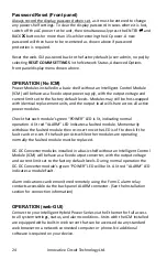
Страница 16: ...o off after approximately 60 minutes of no use and can be re activated by momentarily pressing any of the front control buttons Figure 9 ICM Front Control Interface System Status Screen The ICM Interf...

Страница 17: ...t A Flashing when at the set current limit Other information will be shown depending on the operating state of the unit A small thermometer symbol to indicate that the remote temperature sensor is ins...

Страница 18: ...The BMM Status Screen indicates the Battery Voltage VDC the combined Battery Current A for charging A for discharging the approximate battery State of Charge SOC and a bar graph showing relative magni...

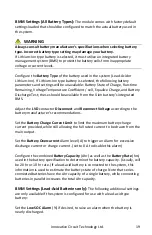
Страница 19: ...LVD contactor Disconnect and Reconnect Voltage according to the battery manufacturer s recommendations Set the Battery Charge Current Limit to limit the maximum battery charge current provided while s...

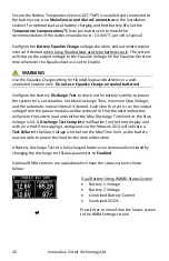
Страница 20: ...Discharge Test to check on the battery s ability to power the system for a set duration Set Max Discharge Time minimum Stop Voltage and the automatic repeat Interval if desired Each time the test is r...

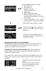
Страница 21: ...nge then press Enter to adjust the setting Scroll to highlight parameter to change LVD Disconnect V LVD Reconnect V Charge Current Limit Over Current Alarm level Battery Type Battery Capacity Ahr rati...

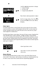
Страница 22: ...o activate the alarm inputs using the web GUI Alarms Settings Control tab The factory default setting has the alarm inputs disabled you must select a contact type for each input to enable it Alarm His...

Страница 23: ...mm Control Restart to restart the controller without affecting any of the device settings and without interrupting DC power to the output terminals or Reset Comm Settings sets GUI password Communicati...

Страница 24: ...h module s green POWER LED is lit indicating normal operation A lit red ALARM LED indicates a faulted module Momentarily withdraw the faulted module then re insert once the LED is off to check if the...

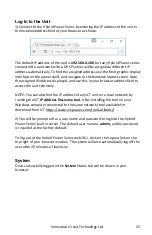
Страница 25: ...d to access the unit remotely NOTE You can also find the IP address of any ICT unit on a local network by running the ICT IP Address Discovery tool After installing the tool on your Windows computer c...

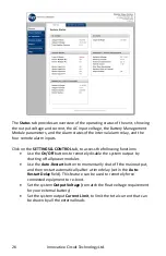
Страница 26: ...llowing functions Use the On Off buttons to remotely disable the system output by shutting off all power modules Use the Auto Restart button to momentarily shut off the main output and then restart au...

Страница 27: ...see the current status of all installed power modules in the system The combined maximum output capacity of all active power modules is shown here Use the System SETTINGS CONTROL tab to make any chan...

Страница 28: ...You may check battery string voltage combined current is charging is discharging temperature if ICT TMP probe installed Net Ah count approximate Ah discharged from the battery where 0Ah denotes full c...

Страница 29: ...hen selecting battery type Incorrect battery type setting may damage your battery If Lithium Ion type battery is selected an integrated battery management system BMS must be used to protect the batter...

Страница 30: ...a level at least 1 5 V more than the disconnect voltage to prevent the LVD contactor repeatedly cycling on and off This setting will be used when charging the battery from an external DC source such a...

Страница 31: ...ault setting is 0mV assumes 25 C operation Note that the system must have the battery temperature sensor ICT TMP installed on the battery for this setting to have an effect Equalize Charge Settings Th...

Страница 32: ...enabled on the Communications Basic Setup page to enable automatically recurring equalize charges Note that an equalize charge can only be initiated when the battery is fully charged If the system is...

Страница 33: ...gured via the Network GUI indicates the battery is able to power the connected load for the set test duration while maintaining its voltage above the Discharge Voltage Limit The system will indicate a...

Страница 34: ...lected Start Time it will attempt again at the same time next day or next week if a specific Day of Week is selected You may alternatively manually initiate a Battery Discharge Test of a fully charged...

Страница 35: ...and output current of the integrated DC output converter module Click on the SETTINGS CONTROL tab to configure the settings for DC Converter module Integrated DC Output Converter Output Status Use th...

Страница 36: ...ame Give each input a meaningful name to suit the installation these will be used for e mailed alarm messages Contact Type select a Contact Type of either Normally Open NO or Normally Closed NC for ea...

Страница 37: ...hdog timer and data logging features Power System Device Info Device Name for the system used in all email messages and view the Model and hardware version Date and Time Settings Check the system inte...

Страница 38: ...ping response from either IP address before initiating a reset Reset Target Select what output to power cycle if the watchdog times out Set the Auto Restart Delay time on the System Settings Control t...

Страница 39: ...e four of the LCD Network Status screen Enable DHCP Turn on this setting if your network uses a DHCP server to automatically assign IP addresses Enabled as default setting To manually assign a static...

Страница 40: ...range of 1 to 65565 if required HTTP Port This port is used for HTTP traffic between the power system and your browser The default HTTP port is 80 and if you change this the new HTTP Port number must...

Страница 41: ...downloaded from the link at the bottom of the SNMP box on this web GUI page or on the web GUI s Help page or can be downloaded from the ICT Website https www ict power com tools utilities The unique p...

Страница 42: ...rite SNMP access The default write community string is write NOTE The community strings should be changed to unique passwords before enabling SNMP as the defaults are well known SNMPv3 Settings User N...

Страница 43: ...selected enter the authentication password for SNMPv3 traps Privacy Protocol Select the privacy protocol for SNMPv3 traps None or AES Privacy Password If a privacy protocol is selected enter the priv...

Страница 44: ...ter an e mail address that will appear as the sender for all e mail notifications sent from the power system Recipient E mail Addresses Enter one or more e mail addresses that are to receive all e mai...

Страница 45: ...ox to get a notification each time the system output current hits the maximum current limit value Intelligent Controller Module reset Check this box for notification of an ICM reset for any reason The...

Страница 46: ...ser can only view status cannot change any settings New Password Use these fields to change the password of the selected user New Password Enter the new password for the chosen user Confirm New Passwo...

Страница 47: ...ay cause loss of network communications due to loss of custom changes to any network settings To reset only the IP address and Administrator password to the original default values select Reset Comm S...

Страница 48: ...active Router Configuration Use this section to help you set up your Hybrid Power Series with remote Internet access when it is located behind a router A router allows multiple PC s to share a single...

Страница 49: ...HTTPS forwarding by repeating steps 2a to 2e with the HTTPS port number that the power system is using The default HTTPS port number is 443 Router Port Forwarding Screen 4 Determine the WAN IP addres...

Страница 50: ...he alarm e mails to be sent to your mobile phone service provider On the E mail Setup page of the web based utility enter the address of your phone in the Recipient E mail Address field Example with a...

Страница 51: ...tup section See the Password Reset section for details on how to reset the port number to the factory default value If your network switch allows you to manually configure port speed and duplex settin...

Страница 52: ...power modules along with the Form C alarm contacts on the back panel indicate the status of power shelf There is an option on the Setup page in the web GUI for most alarms to make a selection to have...

Страница 53: ...nections open Disabled On Off No PFC Shutdown Internal bus voltage out of range Disabled On Off Active Yes Module Fault Internal aux voltages out of range Disabled On Off Active Yes Over Temp Shutdown...

Страница 54: ...DC DC Converter Module Alarms Alarm Condition Trigger Condition Module Output Red LED Green LED Alarm Relay Send E mail3 Module Power Failure Loss of AC and DC bus connection Disabled Off Off Active...

Страница 55: ...nput Contact open or close on any Alarm input 1 to 4 Active if set up on Alarm Input page Yes AC Input Failure AC input falls below 90Vac Active Yes Shelf Overcurrent Total output current on shelf is...

Страница 56: ...t 100 A BMM Max total Battery Current through LVD 150 A BMM LVD Threshold V Default 21 0 V 42 0 V 21 0 V 42 0 V BMM LVD Reconnect V Default setting 25 V 50 V 25 V 50 V BMM idle DC Power Draw 6 1 W Int...

Страница 57: ...o 70 C Humidity Operating 10 90 non condensing Storage 5 95 non condensing Cooling Load controlled fan on power modules Regulatory Compliance 700W Module UL CSA60950 1 UL CSA 62368 1 ICES 003 FCC Part...

Страница 58: ...f the FCC Rules and ICES 003 These limits are designed to provide reasonable protection against harmful interference in a residential installation This equipment generates uses and can radiate radio f...

Страница 59: ...nt and receiver Connect the equipment into an outlet on a circuit different from that to which the receiver is connected Consult the dealer or an experienced RF technician for help Caution Changes or...

Страница 60: ...such damage Product that is returned as defective which is determined to operate within published specifications will be returned to the Purchaser freight collect ICT assigns to Purchaser any warranti...

Отзывы: