22
minutes duration. The exhaust will have a pungent odor
and produce a white cloud of steam.
3.4)
Perform the smoke / CO2 test:
1. For chimney installations, pierce a test hole in the
smoke pipe near the furnace breech. For side-wall
vented installations, remove the threaded cap from
the extended test pipe that is welded into 4-bolt
breech plate. Insert the smoke test instrument
probe into the open hole.
2. Starting with a zero smoke reading, gradually
reduce the burner air setting until just a trace (#1 on
Bacharach Scale) of smoke results.
3. Take a CO2 sample at the same test location
where the smoke sample was taken. Note the CO2
reading associated with the #1 smoke condition.
4. For chimney vented installations, adjust the burner
air setting to obtain a CO2 reading 1% lower than
the reading associated with the #1 smoke.
5. For side-wall vented installations, adjust the burner
air setting to obtain a CO2 reading 1.5% lower than
the reading associated with the #1 smoke.
1. This method of adjusting the CO2 will allow
adequate excess air to ensure that the burner will
burn clean for the entire heating season, and will
ensure proper calibration of the DV-2000™ blocked
intake/ vent safety shutdown system used in side-
wall venting applications.
3.5)
Perform the supply air temperature
rise test:
1. Operate the burner for at least 10 minutes.
2. Measure the temperature of the air in the return air
plenum.
3. Measure the temperature of the air in the largest
trunk coming off the supply air plenum, just “out of
the line of sight” of the radiation coming off the heat
exchanger; 12” away from the plenum on the main
take-off usually satisfies this objective.
4. The temperature rise is calculated by subtracting
the return air temperature from the supply air
temperature.
5. If the temperature rise exceeds the temperature
specified in table #4.1 to #4.3, change to the next
higher blower speed tap until the temperature rise
falls to at this temperature or below. If the excessive
temperature rise cannot be reduced by increasing
fan speed, investigate for ductwork restriction(s),
dirty or improper air filter, or overfiring caused by
excessive pump pressure, or inproper nozzle
sizing.
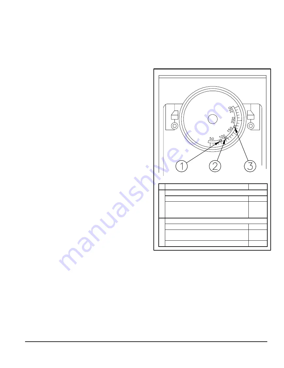
3.6)
Fan limit adjustment:
FIGURE # 4
1
Limit “FAN OFF”
90
0
F
2
Limit “FAN ON”
Model : OLR160
110
0
F
Model : OUF105, OLF105, OLR105,
OUF160, NOUF105, NOLF105 &
NOUF160
130
0
F
3
Limit “HI”
Model: OLR160
170
0
F
Model: OUF105, OLF105, OLR105,
NOUF105 & NOLF105
180
0
F
Model: OUF160 & NOUF160
220
0
F
3.7)
Vent temperature test:
1. Place a thermometer in the test hole located in the
breech pipe.
2. The vent temperature should be between 400 and
575
°
F. If not, check for improper air temperature
rise, pump pressure, nozzle size, or for a badly
sooted heat exchanger.
DNS-0355 Rev.B
Содержание OLR Series
Страница 29: ...DNS 0571 Rev B DNS 0573 Rev B 30 FIGURE 5 1 Model OLR105A12B FIGURE 5 2 Model OLR160B20B...
Страница 30: ...31 FIGURE 5 3 Model OUF105A12B FIGURE 5 4 Model OUF160B18 DNS 0568 Rev C DNS 0572 Rev C...
Страница 31: ...FIGURE 5 5 Model OLF105A12B DNS 0570 Rev B FIGURE 5 6 Model NOUF105A12B 32 DNS 0674 Rev C...
Страница 32: ...33 FIGURE 5 7 Model NOUF160B18B FIGURE 5 8 Model NOLF105A12B DNS 0676 Rev C DNS 0675 Rev D...


