background image

GWA


Gas-Fired Water Boilers – 

Boiler Manual

5

Part Number 670 01 1001 00

Table 2

Corrosive contaminants and likely locations

To prevent potential of severe personal injury or death,
check for products or areas listed below before
installing boiler. If any of these contaminants are found:

• Remove contaminants permanently.

— OR —

• Isolate boiler and provide outside combustion air. See

national, provincial or local codes for fur ther
information.

Please review the following information on potential combustion air
contamination problems.

See Table 2 for products and areas which may cause contaminated
combustion air.

Air contamination

Air openings

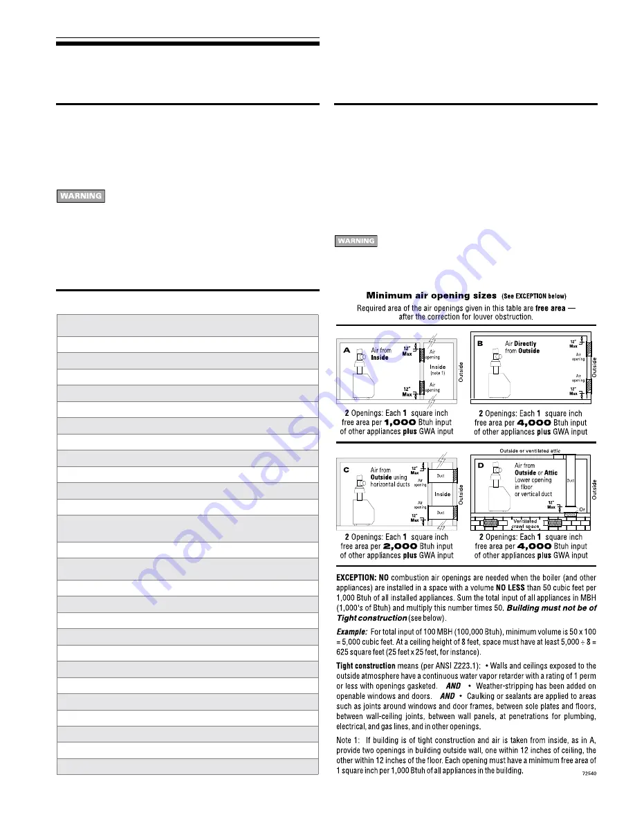
Combustion air and ventilation openings must comply with Section
5.3, “Air for Combustion and Ventilation”, of National Fuel Gas Code
ANSI Z223.1–latest edition, or applicable local building codes.
Canadian installations must comply with B149.1 or B149.2
Installation Codes.

See table below for minimum combustion/ventilation air opening
sizes. Where openings are required, provide two (2) openings —
one within 12 inches of the ceiling, the other within 12 inches of the
floor, as shown in the table illustrations.

Provide adequate combustion and ventilation air to
assure proper combustion and reduce the risk of
severe personal injury, death or substantial property
damage caused by flue gas spillage and carbon
monoxide emissions.

Products to avoid

Spray cans containing chloro/fluorocarbons

Permanent wave solutions

Chlorinated waxes/cleaners

Chlorine-based swimming pool chemicals

Calcium chloride used for thawing

Sodium chloride used for water softening

Refrigerant leaks

Paint or varnish removers

Hydrochloric acid/muriatic acid

Cements and glues

Antistatic fabric softeners used in clothes dryers

Chlorine-type bleaches, detergents, and cleaning solvents found in 
household laundry rooms

Adhesives used to fasten building products and other similar products

Areas likely to have contaminants

Dry cleaning/laundry areas and establishments

Swimming pools

Metal fabrication plants

Beauty shops

Refrigeration repair shops

Photo processing plants

Auto body shops

Plastic manufacturing plants

Furniture refinishing areas and establishments

New building construction

Remodeling areas

Garages with workshops

1

Prepare boiler location 

continued

GWA


Gas-Fired Water Boilers – 

Boiler Manual

32

Part Number 670 01 1001 00

Figure 19

Trim assembly

12 Replacement parts 

continued

Item

number

Description

Manufacturer

Manufacturer’s

par t number

International

Comfort

Products

par t number

1

Pressure relief valve, ASME, 30 PSIG, ¾" male inlet

Pressure relief valve, ASME, 30 PSIG, ¾" female inlet
(Fittings shown are factory-installed on boiler.)

Conbraco

Watts

10-407-10

M330

511546920WT

Conbraco

Watts

10-408-05

335

511546924WT

2

Combination pressure-temperature gauge, with 2½" short
shank

Ametek

ENFM

PTA-1088

4104

510218099WT

3

Drain valve, ¾"
(Fittings shown are included with boiler.)

Conbraco

Hammond Valve

Matco-Norca

Watts

31-606-01

710

205F04

BD-2C

511210423WT

4

Circulator (Fittings shown are shipped loose with boiler.)

Taco

007

511405113WT

5

Circulator gasket, universal (2 per boiler)

International Comfort Products

590317535WT

not

shown

Circulator hardware kit, includes:

2 flanges, 4 nuts, 4 screws, 2 pipe nipples —
1" NPT — GWA052 through GWA140
1¼" NPT — GWA175 through GW245

International Comfort Products

381354525WT
381354526WT

6

Circulator wiring harness

International Comfort Products

591319793WT

Содержание GWA 245

Страница 1: ...Hazards that will or can cause minor personal injury or property damage Special instructions on installation operation or maintenance that are important but not related to personal injury or property...

Страница 2: ......

Страница 3: ...ation dimensions Residential garage installation Take the following special precautions when installing the boiler in a residential garage If the boiler is located in a residential garage per ANSI Z22...

Страница 4: ......

Страница 5: ...n 12 inches of the ceiling the other within 12 inches of the floor as shown in the table illustrations Provide adequate combustion and ventilation air to assure proper combustion and reduce the risk o...

Страница 6: ......

Страница 7: ...ded with boiler 7 Temporarily plug the air elimination tapping next to supply tapping 2 Prepare boiler continued Pressure test Fill and pressure test 1 Open the shutoff valves you installed on supply...

Страница 8: ......

Страница 9: ...the damper blade 3 Install damper harness between damper actuator and hole in jacket left side panel See Figure 3 page 8 Use strain relief connectors and locknuts to secure both ends of damper harnes...

Страница 10: ......

Страница 11: ...ation Failure to prevent low return water temperature to the boiler could cause corrosion of the boiler sections or burners resulting in severe personal injury death or substantial property damage Ins...

Страница 12: ......

Страница 13: ...8 79 150 305 460 150 31 64 120 250 380 1 Remove jacket front panel and see Figure 10 to pipe gas to boiler a Install drip leg at inlet of gas connection to boiler Where local utility requires drip leg...

Страница 14: ......

Страница 15: ...ragm type or bladder type expansion tank systems only one turn 5 Open other vents a Starting on the lowest floor open air vents one at a time until water squirts out b Repeat with remaining vents 6 Re...

Страница 16: ......

Страница 17: ...to verify operation 5 Return thermostat to normal setting 6 Set thermostat heat anticipator setting indicated on wiring diagram Check venting system operation 1 With boiler firing hold a candle or mat...

Страница 18: ......

Страница 19: ...d on boiler Vent damper will remain closed until a call for heat 2 Call for heat When thermostat circuit closes the boiler circulator and vent damper are energized The vent damper drives open When the...

Страница 20: ......

Страница 21: ...inspect the appliance and to replace any part of the control system and any gas control which has been under water 1 Stop Read the safety information above on this label 2 Set the thermostat to lowes...

Страница 22: ......

Страница 23: ...lace it in a plastic bag for disposal Wash potentially contaminated clothes separately from other clothing Rinse clothes washer thoroughly NIOSH stated First Aid Eye Irrigate immediately Breathing Fre...

Страница 24: ......

Страница 25: ...tomatic air vents in systems with closed type tanks The air will escape from the system instead of returning to the tank Eventually the tank will waterlog and no longer control pressurization The boil...

Страница 26: ......

Страница 27: ...ow Lighting Instructions pages 20 and 21 If gas is available and you cannot obtain a pilot flame try purging the gas line and cleaning pilot and pilot gas tubing Follow Lighting Instructions again If...

Страница 28: ......

Страница 29: ...2 GWA070 GWA105 GWA140 GWA175 GWA210 GWA245 450021270WT 450021271WT 450021272WT 450021273WT 450021274WT 450021275WT 450021276WT Item number Description International Comfort Products part number 4 Hig...

Страница 30: ......

Страница 31: ...T 4 Jacket panel door GWA052 GWA070 GWA105 GWA140 GWA175 GWA210 GWA245 431223450WT 431223451WT 431223452WT 431223453WT 431223454WT 431223455WT Item number Description International Comfort Products pa...

Страница 32: ......

Страница 33: ...rt number Standing pilot Natural gas components 1 Gas valve 1 2 x 1 2 GWA052 through GWA175 Gas valve 3 4 x 3 4 GWA210 and GWA245 Honeywell Robertshaw Honeywell VR8200A2116 7200ER VR8300C4050 51104436...

Страница 34: ......

Страница 35: ...after the model number designates natural gas The letter after the N designates the pilot ignition system S for standing pilot or I for spark ignited pilot For example a suffix NS means a natural sta...

Страница 36: ......

Отзывы: