


I-2533 User Manual (ver. 1.1, 2013/05/31) ------12
2.6 Terminator Resistor Setup
In order to minimize the reflection effects on the CAN bus line, the CAN
bus line has to be terminated at both ends by two terminator resistors as in the
following figure. According to the ISO 11898-2 spec, each terminator resistor is
120Ω (or between 108Ω~132Ω). The bus topology and the positions of these
terminator resistors are shown as following figure.
1
2
0
Ω
1
2
0
Ω
CAN_H
CAN_L
Device N
Device 2
Device 1
. . .
Figure 2.5 CAN bus network topology
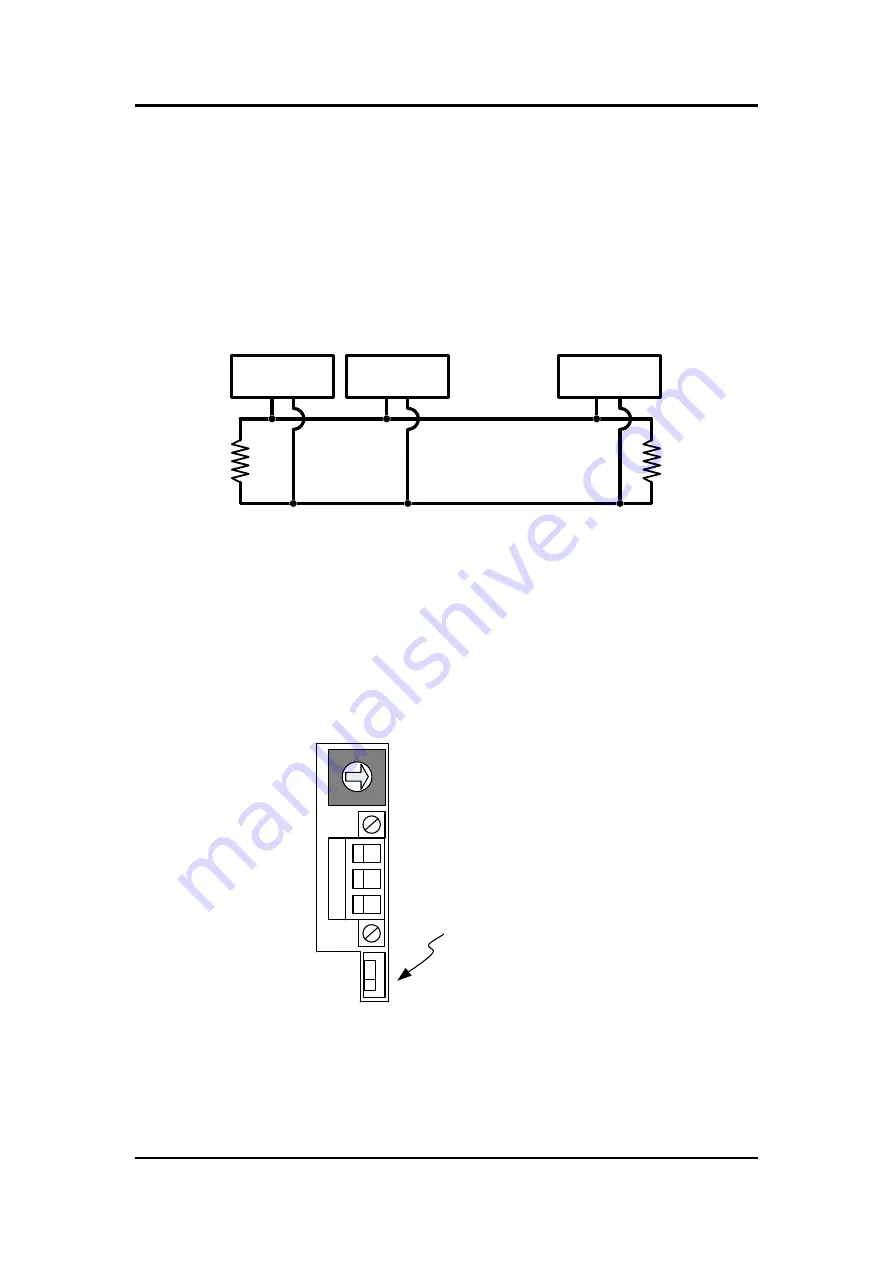
Each I-2533 includes one build-
in 120Ω termintor resistor, users can
decide if it is enabled or not. The DIP switch for terminator resistor is under the
power connector.
8
7
0
C
4
2
1
F
D
B
9
5
3
A
6
E
DIP switch for
terminator resistor
Figure 2-6 Location of Terminator Resistor DIP Switch
The following DIP switch statuses present the condition if the terminator
resistor is active (default) or inactive.


