7-15
DESCRIPTION OF AIRPLANE AND SYSTEMS / INSTRUMENTS
ICON A5 / PILOT’S OPERATING HANDBOOK
CHANGE A3
CHA
P
TER
7
7.6.2 ANGLE OF ATTACK SYSTEM
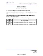
FIGURE 7-5
AOA GAUGE WITH A MID-YELLOW INDICATION
The AOA gauge provides a visual indication of how hard the wing is
working to generate lift and how much more lift it can supply at any
given time. AOA is related to stick position, and so the AOA gauge
can also provide an approximate indication of the current stick
position and how much farther aft it can move before the wing will
stall.
The AOA system works by using static ports to measure the
difference in pressure from the top and bottom of the left wing near
the leading edge. These values are compared and computed to
drive the AOA indicator electrically.
The horizontal line on the gauge depicts optimum AOA during
approach for landing and also maximum lift-to-drag ratio which can
be used for best range performance and best glide. The AOA gauge
can also be used to help guide control inputs to achieve specific
performance objectives during nearly every phase of flight. The
ability to reference AOA during each of these phases allows much
more precise inputs and also provides direct information about how
the wing is performing at any given time. During a turn, the AOA
system provides a direct indication of margin above stall in all
phases of flight. This permits optimization of turn performance
safely and efficiently. For cruise, AOA allows for efficient flight by
providing a simple cue for optimum range performance. The AOA
gauge is disabled at airspeeds below 30 knots.
Содержание A5
Страница 6: ...VI RECORD OF MANUAL HANDBOOK REVISIONS ISSUE A ICON A5 PILOT S OPERATING HANDBOOK ISSUE A3...
Страница 8: ...VIII LIST OF EFFECTIVE CHAPTERS ICON A5 PILOT S OPERATING HANDBOOK ISSUE A3...
Страница 10: ......
Страница 14: ......
Страница 18: ......
Страница 44: ......
Страница 57: ...EMERGENCY PROCEDURES WHEEL BRAKE FAILURE 3 14 CHANGE A2 ICON A5 PILOT S OPERATING HANDBOOK CHAPTER 3...
Страница 58: ......
Страница 73: ...NORMAL PROCEDURES POST FLIGHT INSPECTION 4 16 CHANGE A3 ICON A5 PILOT S OPERATING HANDBOOK CHAPTER 4...
Страница 74: ......
Страница 90: ......
Страница 100: ......
Страница 123: ...DESCRIPTION OF AIRPLANE AND SYSTEMS ICON PARACHUTE SYSTEM 7 24 CHANGE A3 ICON A5 PILOT S OPERATING HANDBOOK CHAPTER 7...
Страница 124: ......
Страница 141: ...HANDLING AND SERVICING CLEANING AND CARE 8 18 CHANGE A1 ICON A5 PILOT S OPERATING HANDBOOK CHAPTER 8...
Страница 142: ......