2
2001 NEW
1
2
3
4
5
6
7
8
9
10
11
12
13
14
15
16
17
Qutck Reneoence
2
PANEL DESCRIPTION
17
16
15
14
13
12
10
11
9
7
8
6
5
4
3
2
Qutck Reneoence
■
Matn unta
q
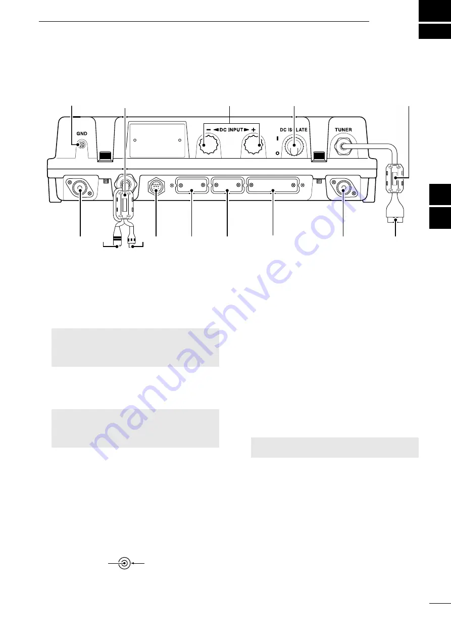
GROUND TERMINAL [GND]
Connect to the ship’s ground. (p. 81)
w
DSC ANTENNA CONNECTER
Connect to a 50 Ω HF marine band antenna
through a 50 Ω coaxial cable with a PL-259 plug.
This antenna is used for receiving Distress calls.
NOTE:
To receive a Distress call,
BE SURE
to connect an HF marine band antenna to this
antenna connector. Otherwise, you cannot
receive any Distress calls.
e
SPEAKER JACK [SP]
Connect to the SP-24 (p. 80) or an external
speaker.
NOTE:
When using an external speaker,
BE
SURE
to turn OFF the internal speaker. (p. 5)
Audio is output from the external speaker only
when the internal speaker is OFF.
r
GPS JACK [GPS]
Connect to a GPS receiver to input position and
UTC data for DSC operations. (IEC 61162-1
Edition 4.0 (2010-11))
• An IEC 61162-1 Edition 4.0 (2010-11) (sentence
formatters: GGA) compatible GPS receiver is
required. Ask your dealer about suitable GPS
receivers.
GPS IN (+)
RCA
GPS IN (–)
t
CONTROLLER CONNECTOR [CONTROLLER]
Connect to the supplied controller.
y
MODEM SOCKET [AF/MOD] (p. 87)
Connect to an external terminal unit for SSB
mode operation through an RS-232C cable
(D-sub 15-pin).
u
REMOTE SOCKET [REMOTE] (p. 88)
Connect to a PC through an RS-232C cable
(D-sub 9-pin) for remote control.
i
PRINTER CONNECTOR
Connect to an IBM
®
centronics or compatible
printer to automatically or manually print out
received DSC information.
o
ANTENNA CONNECTOR
Connect to a wire or whip antenna through the
AT-141
hf
automatic
antenna
tuner
. The
antenna is used for transmitting any calls and
receiving any calls other than Distress calls.
R
WARNING! NEVER
directly connect the
antenna to this connector.
!0
TUNER CONTROL SOCKET [TUNE]
Connect to the control cable of the supplied
AT-141
hf
automatic
antenna
tuner
. A female
connector kit is supplied to connect the AT-141.
!1
POWER SWITCH [DC ISOLATE]
Turns the transceiver’s main power ON or OFF.
When the main power is ON, the power key's
backlight is dimly lit.
!2
DC POWER TERMINALS
Connect to a 24 V DC power source through the
supplied DC power cables. The red terminal is
positive (+) and the black terminal is negative (
–
).
q
t
!2
!1
!0
o
i
u
y
r
w
e
FERRITE EMI FILTER
FERRITE EMI FILTER


