19
5.7
BURNER CONNECTION
Before installation you are advised to thoroughly clean the inside of all the fuel supply system pipes in order
to remove any foreign matter that could affect correct operation of the boiler. See technical specification ta-
bles and check the max pressure value inside the furnace. The value found on the table may also increase
by 20% if heavy oil is used instead of gas or light oil; furthermore the following checks should also be carried
out:
a) Check the internal and external seal of the fuel supply system;
b) Regulate the fuel flow according to the power required by the boiler;
c) Check that the boiler is fired by the correct type of fuel;
d) Check that the fuel supply pressure is within the values specified on the burner rating plate;
e) Check that the fuel supply system is sized for the maximum flow rate necessary for the boiler and that it
is provided with all control and safety devices provided for by the regulations referred to above;
In particular, when using gas:
f)
Check that the supply pipe and the gas ramp comply with the regulations in force;
g) Check that all the gas connections are sealed;
h) Check that the boiler room vents are of sufficient size to ensure the air flow dictated by the regulations
referred to above and that they are in any case sufficient to obtain perfect combustion.
i)
Check that the gas pipes are not used as earth connections for electrical appliances.
If the boiler is not going to be used for some time, close the fuel supply cock or cocks.
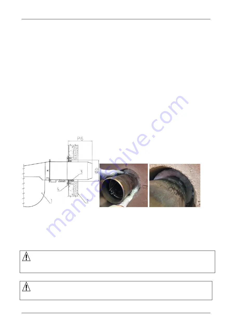
IMPORTANT: check that the gap between the burner draught tube and the mounting plate are prop-
erly filled with thermoinsulating material.
The thermoinsulating strip provided with the boiler must be wrapped around the mouthpiece for at least an
entire circumference of the flame radiation to protect the flange of the burner. Not that the ceramic insulation
is necessary to fill the gap until the insulation inside surface of the door.
The above picture is only for reference.
KEY:
1. Burner
2. Manhole
3. Thermoinsulating
material
4. Flange
All details on the draught tube lenght (
P6
), the diameter of the burner hole (
Øb
) and the pressurization are included
in the par. Technical Specifications.
ATTENTION:
when using oil or bio-gas for operation, the door must have ce-
ment insulation and special tie rods. Any alterations and/or lack of commu-
nication during the selling phase shall nullify the warranty conditions.
GREENOX BT COND:
ATTENTION: The boiler is designed for use with NATURAL GAS and
LPG. The use of other fuels will void the boiler warranty.
Содержание GREENOx.e Series
Страница 31: ......


