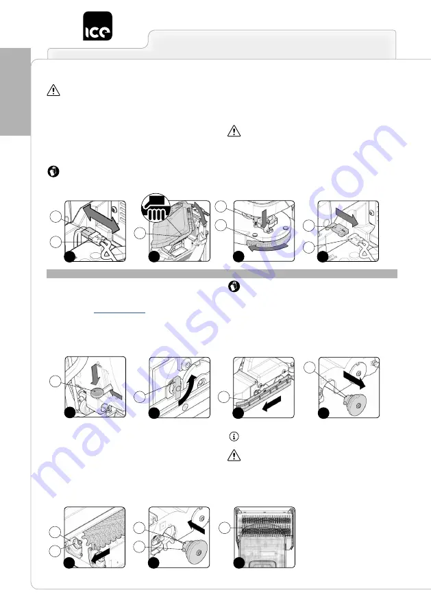
30
PREP
ARING THE
APPLIANCE
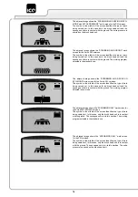
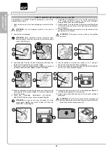
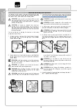
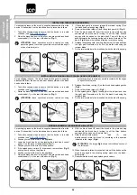
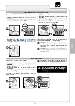
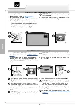
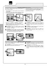
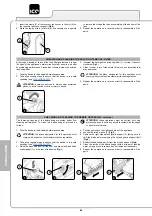
14. Disconnect the connector of the general system (8) from the
connector of the batteries (9) (
Fig.9
).
ATTENTION:
This process must be carried out by qualified
personnel.
15. Grip the handle (7) on the left side of the recovery tank and turn
the tank until it reaches the work position (
Fig.10
).
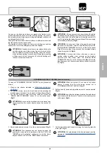
16. With the brush head UP, insert the brush in the plate housing
underneath the brush head, turning it until the three buttons
engage with the niches on the plate itself.
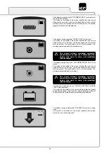
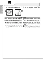
17. Press the brush-holder plate latch (10) and simultaneously rotate
the brush (11) according to the direction indicated in the image
(
Fig.11
).
ATTENTION:
The image
Fig.11
shows the rotation direction
of the left brush.
18. When the brush rotation is prevented, turn until the button on the
brush is engaged in the coupling spring, present on the brush-
holder plate.
19. Grip the handle (7) on the left side of the recovery tank (
Fig.7
) and
turn the tank as far as it will go, until it reaches the maintenance
position (
Fig.8
).
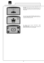
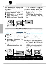
20. Connect the connector of the general system (8) from the
connector of the batteries (9) (
Fig.12
).
ATTENTION:
This process must be carried out by qualified
personnel.
21. Grip the handle (7) on the left side of the recovery tank and turn
the tank until it reaches the work position (
Fig.10
).
INSTALLING THE BRUSH (50C versions)
For packaging reasons, the brush is supplied disassembled from the
device. To assemble it on the brush head unit, proceed as follows:
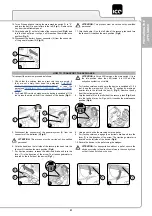
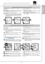
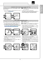
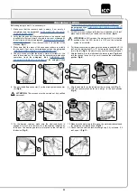
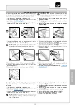
1. Take all necessary steps to ensure that the device is in a safe
’”).
2.
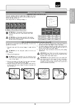
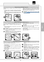
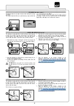
Raise the brush head unit off the floor and press the brush head
control pedal (1) on the rear of the device (
Fig.1
).
ATTENTION:
these operations must be carried out using
protective gloves to avoid any possible contact with the edges
or tips of metal objects.
3. Position yourself on the right-hand side of the appliance.
4. Loosen the retainer knob (2) (
Fig.2
).
5. Remove the right side splash guard support (3), taking care to
shift the blade before removing the splash guard support itself
(
Fig.3
).
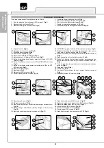
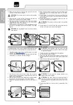
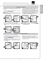
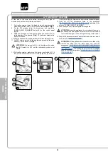
6. Remove the rear brush guide hub (4) (
Fig.4
).
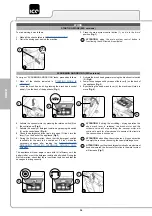
7. Insert the rear brush into the tunnel, taking care to properly
position the drive pins (5) present on the guide hub (6) in the slits
present on the brush (
Fig. 5
).
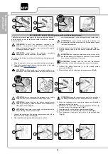
8. Insert the hub (4) into the brush, taking care to properly position
the drive pins (7) in the slits present on the brush (
Fig. 6
).
9. Repeat the operations described above for the front brush as
well.
ATTENTION:
The rear brush (8) (working direction) must
always be the blue one (
Fig.7
).
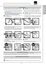
ATTENTION:
The brush bristles are properly positioned if
they form a rhombus when viewed from above. The top of the
shortest height must be positioned towards the front of the
appliance.
10. Repeat the operations in reverse order to reassemble all the
parts.
8
9
9
7
11
10
8
9
12
1
1
4
4
2
3
2
3
5
6
7
4
8
6
7
5
10
11

