


Rev AA
Maintaining the CLARiTY Controller 5-7
4
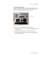
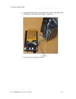
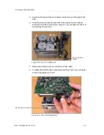
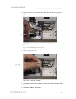
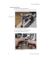
Remove and retain the two screws securing the PCB (Figure 5-7).
5
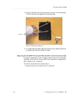
Gently slide and lift the PCB away from the LCD and touch screen
assembly taking care not to damage the three cables coming from the
LCD/Touchscreen module.
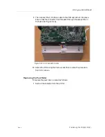
If replacing the Processor PCB then refer to section 13 below. If replacing
the LCD/Touchscreen Assembly then continue below.
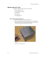
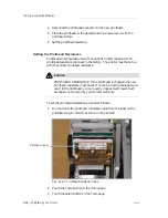
Replacing the LCD/Touchscreen Assembly
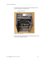
6
Remove and retain the three screws and anti-vibration washers
holding the whole assembly and inverter module. Remove this
module from the case, taking care not to remove the seal around the
Figure 5-7: PCB Connections
Screws
ICE
P
egasus
Service Manual