193
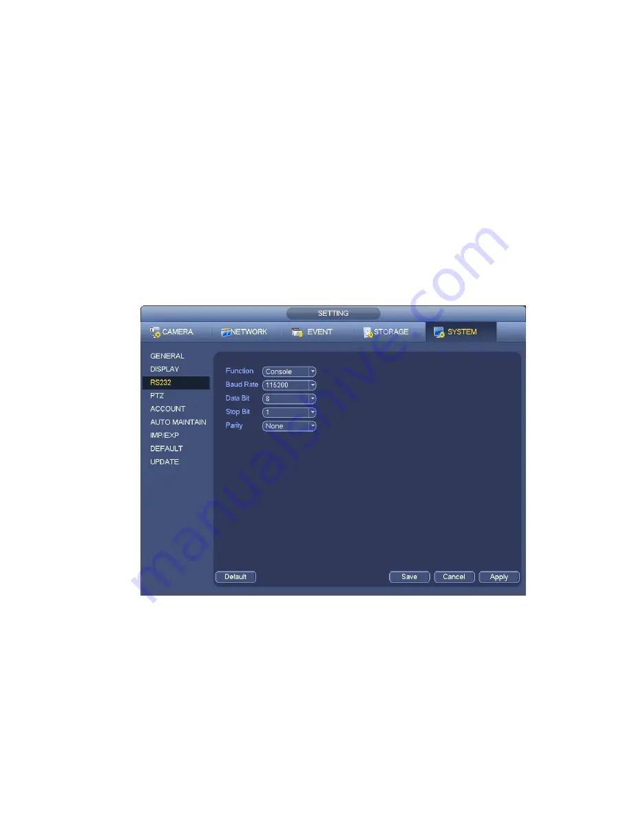
Function: There are various devices for you to select. Console is for you to use the COM or mini-end
software to upgrade or debug the program. The control keyboard is for you to control the device via
the special keyboard. Transparent COM (adapter) is to connect to the PC to transfer data directly.
Protocol COM is for card overlay function. Network keyboard is for you to use the special keyboard
to control the device. PTZ matrix is to connect to the peripheral matrix control.
Baud rate: You can select proper baud rate.
Data bit: You can select proper data bit. The value ranges from 5 to 8.
Stop bit: There are three values: 1/1.5/2.
Parity: there are five choices: none/odd/even/space mark.
System default setup is:
Function: Console
Baud rate:115200
Data bit:8
Stop bit:1
Parity: None
After completing all the setups please click save button, system goes back to the previous menu.
Figure 4-142
4.14.7
Auto Maintain
Here you can set auto-reboot time and auto-delete old files setup. You can set to delete the files for the
specified days. See Figure 4-143.
You can select proper setup from dropdown list.
After all the setups please click save button, system goes back to the previous menu.
Содержание NVR11 Series
Страница 1: ...Network Video Recorder User s Manual V 1 3 0...
Страница 11: ...x Accessories Check the following accessories after opening the box Please refer to the packing list in the box...
Страница 34: ...23 Dimensio n 3U case 448mm 490mm 133 2mm Weight 10 5kg 11 5kg Exclude HDD Installatio n Desk installation...
Страница 91: ...80 Figure 3 9 3 5 10 NVR78 Series Please refer to Figure 3 10 for connection sample...
Страница 92: ...81 Figure 3 10 3 5 11 NVR78 16P Series Please refer to Figure 3 11 for connection sample...
Страница 93: ...82 Figure 3 11 3 5 12 NVR78 RH Series Please refer to Figure 3 12 for connection sample...
Страница 94: ...83 Figure 3 12 3 5 13 NVR70 Series Please refer to Figure 3 13 for connection sample...
Страница 95: ...84 Figure 3 13 3 5 14 NVR70 R Series Please refer to Figure 3 14 for connection sample...
Страница 96: ...85 Figure 3 14...
Страница 151: ...140 Figure 4 74 Figure 4 75...
Страница 152: ...141 Figure 4 76 Figure 4 77...
Страница 158: ...147 Figure 4 82 Figure 4 83...
Страница 159: ...148 Figure 4 84 Figure 4 85...
Страница 160: ...149 Figure 4 86 Figure 4 87...
Страница 162: ...151 Figure 4 89 Figure 4 90...
Страница 165: ...154 Figure 4 92 Figure 4 93 4 11 1 1 Connection The connection setup interface is shown as in Figure 4 94...
Страница 185: ...174 Figure 4 116 In Figure 4 116 click one HDD item the S M A R T interface is shown as in Figure 4 117 Figure 4 117...
Страница 200: ...189 Figure 4 136 Figure 4 137 4 14 3 1 Add Modify Group...
Страница 241: ...230 Figure 5 53 Figure 5 54...
Страница 242: ...231 Figure 5 55 Figure 5 56 Figure 5 57...
Страница 246: ...235 Figure 5 61 Figure 5 62...


