169
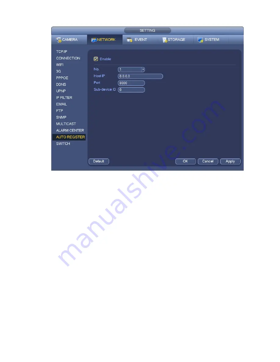
Figure 4-110
2) The proxy server software developed from the SDK. Please open the software and input the global
setup. Please make sure the auto connection port here is the same as the port you set in the previous
step.
3) Now you can add device. Please do not input default port number such as the TCP port in the mapping
port number. The device ID here shall be the same with the ID you input in Figure 4-110. Click Add button
to complete the setup.
4) Now you can boot up the proxy server. When you see the network status is Y, it means your
registration is OK. You can view the proxy server when the device is online.
Important
The server IP address can also be domain. But you need to register a domain name before you run proxy
device server.
4.11.1.14 SWITCH
It is for you to set IP address, subnet mask, gateway and etc of the Switch. See Figure 4-111.
Содержание NVR11 Series
Страница 1: ...Network Video Recorder User s Manual V 1 3 0...
Страница 11: ...x Accessories Check the following accessories after opening the box Please refer to the packing list in the box...
Страница 34: ...23 Dimensio n 3U case 448mm 490mm 133 2mm Weight 10 5kg 11 5kg Exclude HDD Installatio n Desk installation...
Страница 91: ...80 Figure 3 9 3 5 10 NVR78 Series Please refer to Figure 3 10 for connection sample...
Страница 92: ...81 Figure 3 10 3 5 11 NVR78 16P Series Please refer to Figure 3 11 for connection sample...
Страница 93: ...82 Figure 3 11 3 5 12 NVR78 RH Series Please refer to Figure 3 12 for connection sample...
Страница 94: ...83 Figure 3 12 3 5 13 NVR70 Series Please refer to Figure 3 13 for connection sample...
Страница 95: ...84 Figure 3 13 3 5 14 NVR70 R Series Please refer to Figure 3 14 for connection sample...
Страница 96: ...85 Figure 3 14...
Страница 151: ...140 Figure 4 74 Figure 4 75...
Страница 152: ...141 Figure 4 76 Figure 4 77...
Страница 158: ...147 Figure 4 82 Figure 4 83...
Страница 159: ...148 Figure 4 84 Figure 4 85...
Страница 160: ...149 Figure 4 86 Figure 4 87...
Страница 162: ...151 Figure 4 89 Figure 4 90...
Страница 165: ...154 Figure 4 92 Figure 4 93 4 11 1 1 Connection The connection setup interface is shown as in Figure 4 94...
Страница 185: ...174 Figure 4 116 In Figure 4 116 click one HDD item the S M A R T interface is shown as in Figure 4 117 Figure 4 117...
Страница 200: ...189 Figure 4 136 Figure 4 137 4 14 3 1 Add Modify Group...
Страница 241: ...230 Figure 5 53 Figure 5 54...
Страница 242: ...231 Figure 5 55 Figure 5 56 Figure 5 57...
Страница 246: ...235 Figure 5 61 Figure 5 62...


