201
Parameter Function
Preset
Select Preset from the dropdown list.
Turn the camera to the corresponding position and Input the
preset value. Click Add button to add a preset.
Tour
Select Tour from the dropdown list.
Input preset value in the column. Click Add preset button, you
have added one preset in the tour.
Repeat the above procedures you can add more presets in one
tour.
Or you can click delete preset button to remove one preset from
the tour.
Pattern
Select Pattern from the dropdown list.
You can input pattern value and then click Start button to begin
PTZ movement such as zoom, focus, iris, direction and etc. Then
you can click Add button to set one pattern.
Aux
Please input the corresponding aux value here.
You can select one option and then click AUX on or AUX off
button.
Light and
wiper
You can turn on or turn off the light/wiper.
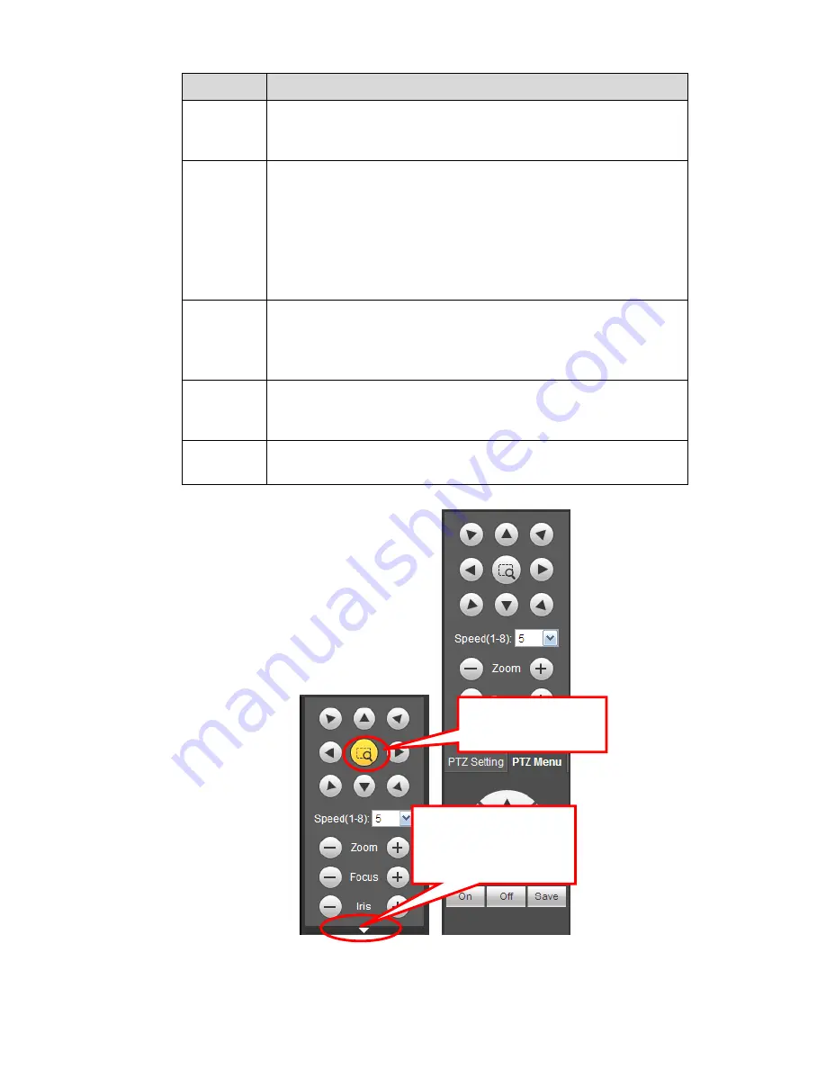
Figure 5-12
You can click this icon to
display or hide the PTZ
control platform.
3D Intelligent Positioning
Key
Содержание NVR11 Series
Страница 1: ...Network Video Recorder User s Manual V 1 3 0...
Страница 11: ...x Accessories Check the following accessories after opening the box Please refer to the packing list in the box...
Страница 34: ...23 Dimensio n 3U case 448mm 490mm 133 2mm Weight 10 5kg 11 5kg Exclude HDD Installatio n Desk installation...
Страница 91: ...80 Figure 3 9 3 5 10 NVR78 Series Please refer to Figure 3 10 for connection sample...
Страница 92: ...81 Figure 3 10 3 5 11 NVR78 16P Series Please refer to Figure 3 11 for connection sample...
Страница 93: ...82 Figure 3 11 3 5 12 NVR78 RH Series Please refer to Figure 3 12 for connection sample...
Страница 94: ...83 Figure 3 12 3 5 13 NVR70 Series Please refer to Figure 3 13 for connection sample...
Страница 95: ...84 Figure 3 13 3 5 14 NVR70 R Series Please refer to Figure 3 14 for connection sample...
Страница 96: ...85 Figure 3 14...
Страница 151: ...140 Figure 4 74 Figure 4 75...
Страница 152: ...141 Figure 4 76 Figure 4 77...
Страница 158: ...147 Figure 4 82 Figure 4 83...
Страница 159: ...148 Figure 4 84 Figure 4 85...
Страница 160: ...149 Figure 4 86 Figure 4 87...
Страница 162: ...151 Figure 4 89 Figure 4 90...
Страница 165: ...154 Figure 4 92 Figure 4 93 4 11 1 1 Connection The connection setup interface is shown as in Figure 4 94...
Страница 185: ...174 Figure 4 116 In Figure 4 116 click one HDD item the S M A R T interface is shown as in Figure 4 117 Figure 4 117...
Страница 200: ...189 Figure 4 136 Figure 4 137 4 14 3 1 Add Modify Group...
Страница 241: ...230 Figure 5 53 Figure 5 54...
Страница 242: ...231 Figure 5 55 Figure 5 56 Figure 5 57...
Страница 246: ...235 Figure 5 61 Figure 5 62...


