204
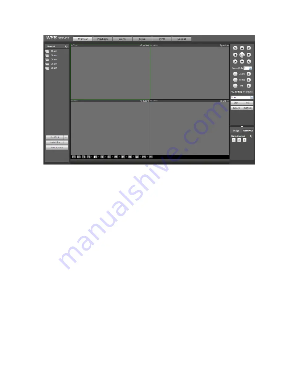
Figure 5-17.
Figure 5-17
Important
The window display mode and the channel number are by default. For example, for the 16-channel,
the max window split mode is 16.
3) Multiple-channel monitor, system adopts extra stream to monitor by default. Double click one channel,
system switches to single channel and system uses main stream to monitor. You can view there are two
icons at the left top corner of the channel number for you reference. M stands for main stream. S stands
for sub stream (extra stream).
4) If you login via the WAN mode, system does not support alarm activation to open the video function in
the Alarm setup interface.
Important
For multiple-channel monitor mode, system adopts extra stream to monitor by default. You can not
modify manually. All channels are trying to synchronize. Please note the synchronization effect still
depends on your network environments.
For bandwidth consideration, system can not support monitor and playback at the same time.
System auto closes monitor or playback interface when you are searching setup in the configuration
interface. It is to enhance search speed.
5.8 Setup
5.8.1
Camera
5.8.1.1 Remote Device
Remote device interface is shown as below. See Figure 5-18.
Содержание NVR11 Series
Страница 1: ...Network Video Recorder User s Manual V 1 3 0...
Страница 11: ...x Accessories Check the following accessories after opening the box Please refer to the packing list in the box...
Страница 34: ...23 Dimensio n 3U case 448mm 490mm 133 2mm Weight 10 5kg 11 5kg Exclude HDD Installatio n Desk installation...
Страница 91: ...80 Figure 3 9 3 5 10 NVR78 Series Please refer to Figure 3 10 for connection sample...
Страница 92: ...81 Figure 3 10 3 5 11 NVR78 16P Series Please refer to Figure 3 11 for connection sample...
Страница 93: ...82 Figure 3 11 3 5 12 NVR78 RH Series Please refer to Figure 3 12 for connection sample...
Страница 94: ...83 Figure 3 12 3 5 13 NVR70 Series Please refer to Figure 3 13 for connection sample...
Страница 95: ...84 Figure 3 13 3 5 14 NVR70 R Series Please refer to Figure 3 14 for connection sample...
Страница 96: ...85 Figure 3 14...
Страница 151: ...140 Figure 4 74 Figure 4 75...
Страница 152: ...141 Figure 4 76 Figure 4 77...
Страница 158: ...147 Figure 4 82 Figure 4 83...
Страница 159: ...148 Figure 4 84 Figure 4 85...
Страница 160: ...149 Figure 4 86 Figure 4 87...
Страница 162: ...151 Figure 4 89 Figure 4 90...
Страница 165: ...154 Figure 4 92 Figure 4 93 4 11 1 1 Connection The connection setup interface is shown as in Figure 4 94...
Страница 185: ...174 Figure 4 116 In Figure 4 116 click one HDD item the S M A R T interface is shown as in Figure 4 117 Figure 4 117...
Страница 200: ...189 Figure 4 136 Figure 4 137 4 14 3 1 Add Modify Group...
Страница 241: ...230 Figure 5 53 Figure 5 54...
Страница 242: ...231 Figure 5 55 Figure 5 56 Figure 5 57...
Страница 246: ...235 Figure 5 61 Figure 5 62...


