93
Click Device search button, you can view the searched IP addresses at the top pane of the interface.
Double click an IP address or check one IP address and then click Add button, you can add current
device to the bottom pane of the interface. System supports batch add function.
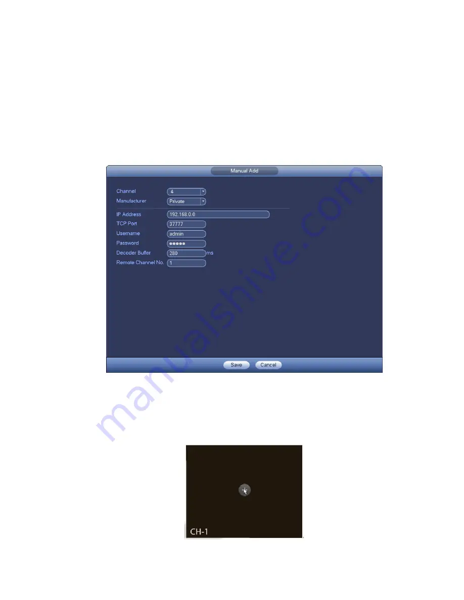
Click Manual Add button, you can add a device directly. Here you can set TCP/UPD/auto connection
mode. The default setup is TCP. See Figure 4-13.
Important
Please note the manual add function is for Dahua, Panasonic, Sony, Dynacolor, Samsung, AXIS, Arecont,
ONVIF and Custom. When the type is the custom, you can just input URL address, user name and
password connect to the network camera without considering network camera manufacture. Please
contact your network camera manufacturer for the URL address.
Figure 4-13
4.4.2
Short-Cut Menu
In the preview interface, for the channel of no IPC connection, you can click the icon “+” in the centre of
the interface to quickly go to the Remote Device interface. See Figure 4-14.
Figure 4-14
Содержание NVR11 Series
Страница 1: ...Network Video Recorder User s Manual V 1 3 0...
Страница 11: ...x Accessories Check the following accessories after opening the box Please refer to the packing list in the box...
Страница 34: ...23 Dimensio n 3U case 448mm 490mm 133 2mm Weight 10 5kg 11 5kg Exclude HDD Installatio n Desk installation...
Страница 91: ...80 Figure 3 9 3 5 10 NVR78 Series Please refer to Figure 3 10 for connection sample...
Страница 92: ...81 Figure 3 10 3 5 11 NVR78 16P Series Please refer to Figure 3 11 for connection sample...
Страница 93: ...82 Figure 3 11 3 5 12 NVR78 RH Series Please refer to Figure 3 12 for connection sample...
Страница 94: ...83 Figure 3 12 3 5 13 NVR70 Series Please refer to Figure 3 13 for connection sample...
Страница 95: ...84 Figure 3 13 3 5 14 NVR70 R Series Please refer to Figure 3 14 for connection sample...
Страница 96: ...85 Figure 3 14...
Страница 151: ...140 Figure 4 74 Figure 4 75...
Страница 152: ...141 Figure 4 76 Figure 4 77...
Страница 158: ...147 Figure 4 82 Figure 4 83...
Страница 159: ...148 Figure 4 84 Figure 4 85...
Страница 160: ...149 Figure 4 86 Figure 4 87...
Страница 162: ...151 Figure 4 89 Figure 4 90...
Страница 165: ...154 Figure 4 92 Figure 4 93 4 11 1 1 Connection The connection setup interface is shown as in Figure 4 94...
Страница 185: ...174 Figure 4 116 In Figure 4 116 click one HDD item the S M A R T interface is shown as in Figure 4 117 Figure 4 117...
Страница 200: ...189 Figure 4 136 Figure 4 137 4 14 3 1 Add Modify Group...
Страница 241: ...230 Figure 5 53 Figure 5 54...
Страница 242: ...231 Figure 5 55 Figure 5 56 Figure 5 57...
Страница 246: ...235 Figure 5 61 Figure 5 62...


