102
Item
Note
lack brightness while the bright section may over exposure .The
recommended value ranges from 40 to 60.
Saturation
It is to adjust monitor window saturation. The value ranges from
0 to 100. The default value is 50.
The larger the number, the strong the color is. This value has
no effect on the general brightness of the whole video. The
video color may become too strong if the value is too high. For
the grey part of the video, the distortion may occur if the white
balance is not accurate. Please note the video may not be
attractive if the value is too low. The recommended value
ranges from 40 to 60.
Gain
The gain adjust is to set the gain value. The default value may
vary due to different device models. The smaller the value, the
low the noise. But the brightness is also too low in the dark
environments. It can enhance the video brightness if the value
is high. But the video noise may become too clear.
Color mode
It includes several modes such as standard, color, bright,
gentle. Select a color mode, the sharpness, brightness,
contrast and etc can automatically switch to corresponding
setup.
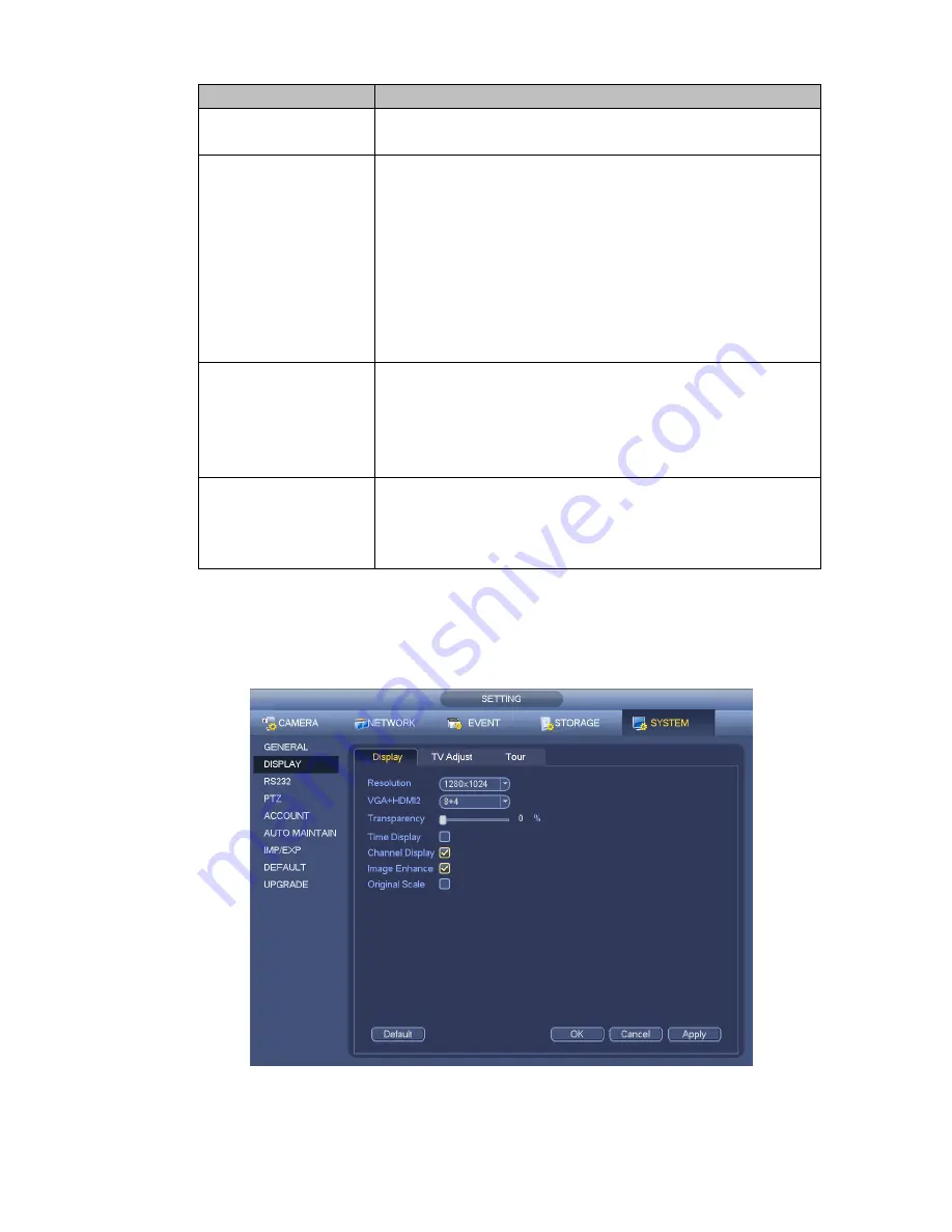
4.5.4.2 Display
From Main Menu->Setting->System->Display, you can go to the following interface. See Figure 4-26.
Here you can set menu and video preview effect. All you operation here does not affect the record file and
playback effect.
Figure 4-26
Now you can set corresponding information.
Содержание NVR11 Series
Страница 1: ...Network Video Recorder User s Manual V 1 3 0...
Страница 11: ...x Accessories Check the following accessories after opening the box Please refer to the packing list in the box...
Страница 34: ...23 Dimensio n 3U case 448mm 490mm 133 2mm Weight 10 5kg 11 5kg Exclude HDD Installatio n Desk installation...
Страница 91: ...80 Figure 3 9 3 5 10 NVR78 Series Please refer to Figure 3 10 for connection sample...
Страница 92: ...81 Figure 3 10 3 5 11 NVR78 16P Series Please refer to Figure 3 11 for connection sample...
Страница 93: ...82 Figure 3 11 3 5 12 NVR78 RH Series Please refer to Figure 3 12 for connection sample...
Страница 94: ...83 Figure 3 12 3 5 13 NVR70 Series Please refer to Figure 3 13 for connection sample...
Страница 95: ...84 Figure 3 13 3 5 14 NVR70 R Series Please refer to Figure 3 14 for connection sample...
Страница 96: ...85 Figure 3 14...
Страница 151: ...140 Figure 4 74 Figure 4 75...
Страница 152: ...141 Figure 4 76 Figure 4 77...
Страница 158: ...147 Figure 4 82 Figure 4 83...
Страница 159: ...148 Figure 4 84 Figure 4 85...
Страница 160: ...149 Figure 4 86 Figure 4 87...
Страница 162: ...151 Figure 4 89 Figure 4 90...
Страница 165: ...154 Figure 4 92 Figure 4 93 4 11 1 1 Connection The connection setup interface is shown as in Figure 4 94...
Страница 185: ...174 Figure 4 116 In Figure 4 116 click one HDD item the S M A R T interface is shown as in Figure 4 117 Figure 4 117...
Страница 200: ...189 Figure 4 136 Figure 4 137 4 14 3 1 Add Modify Group...
Страница 241: ...230 Figure 5 53 Figure 5 54...
Страница 242: ...231 Figure 5 55 Figure 5 56 Figure 5 57...
Страница 246: ...235 Figure 5 61 Figure 5 62...


