Roadside Emergencies
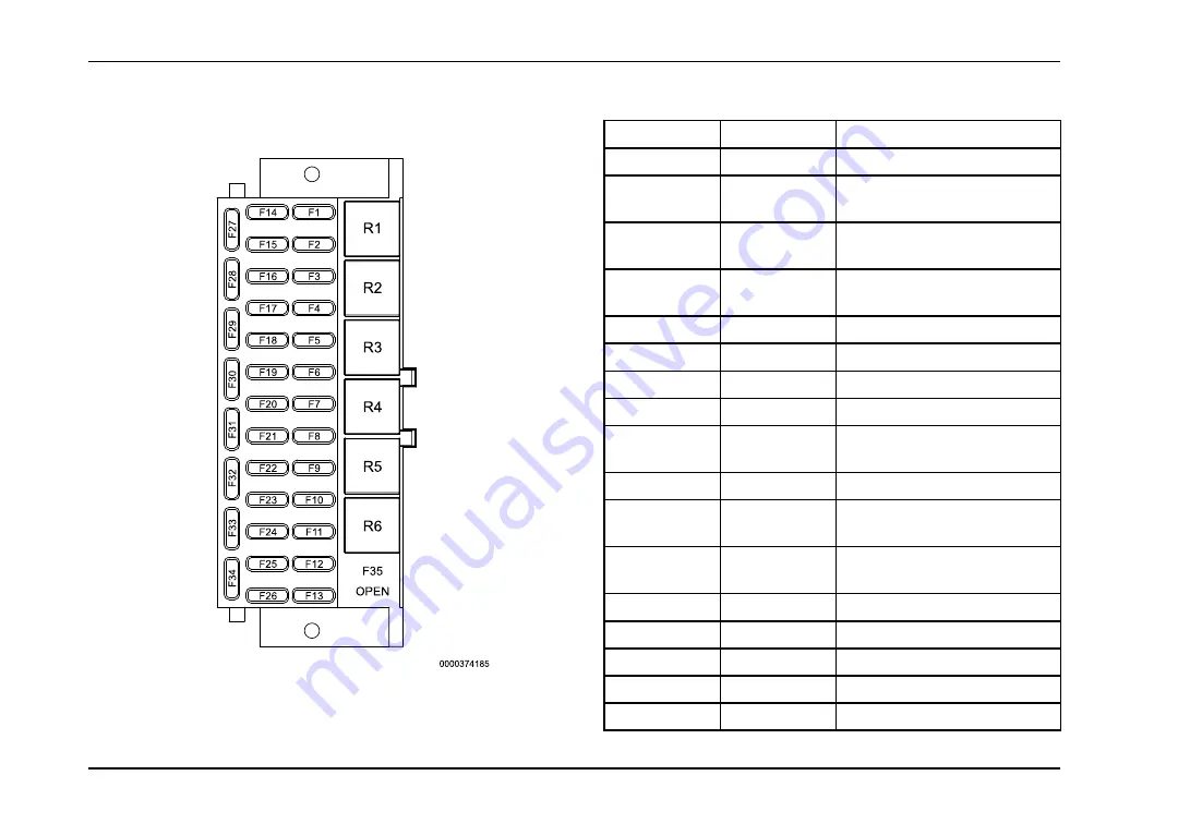
Chassis Fuse / Circuit Breaker Chart
Table 9
Location
Size
Description
F1
10A
Crossing Gate
F2
15A
Instrument Panel Gauge Cluster
Battery Feed
F3
5A *
Hydraulic Brake Switch Battery
Feed
F4
10A
Ammeter / Crossing Gate
Battery Feed
F5
10A
Stop Light Relay Battery Feed
F6
30A
Air Conditioner Blower Motor
F7
10A
Key Switch Battery Feed
F8
3A
Ignition #1 Relay
F9
10A
Diagnostic Connector Battery
Feed
F10
30A
Ignition #2 Relayd
F11
5A*
Body Builder / NEC GPS
Prewire
F12
5A*
System Controller / Switch Pack
Accessory Feed
F13
5A*
Aware
F14
5A*
Body Builder Ignition Feed
F15
10A
Compass Module / Aware
F16
10A
System Controller Ignition Feed
F17
5A*
Engine Electronics Ignition Feed
136
Содержание BE Series
Страница 4: ......
Страница 11: ...Table of Contents Section 14 Index Index 215 vii ...
Страница 12: ...Table of Contents viii ...
Страница 52: ...Instrumentation Declination Zone Map 40 ...
Страница 67: ...Driver Controls 55 ...
Страница 68: ...Driver Controls 56 ...
Страница 71: ...Driver Controls 59 ...
Страница 144: ...Operation 132 ...
Страница 151: ...Roadside Emergencies Body Fuse Circuit Breaker Panel 139 ...


