background image


62

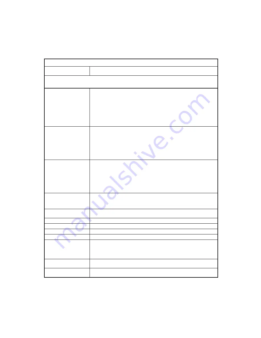
Table 2-1 BIOS Error Codes, Messages, and Beeps List  

BIOS Error Codes, 
Messages, beeps 

Action/FRU 

NOTE: 

To diagnose a problem, first find the BIOS error messages, codes, or beeps in left column.  If directed to a check 

procedure, replace the FRU indicated in the check procedure. If no check procedure is indicated, the first Action/FRU listed 
in right column is the most likely cause. 

1762  
Primary master IDE has 
changed 
Primary slave IDE has changed 
Secondary master IDE has 
changed 
Secondary slave IDE has 
changed 

Make sure that the System Boot Drive parameter in the Startup Options of BIOS Setup is 
not set to [Drive A only].  
Load default settings in Setup. 
Insert a system diskette into diskette drive and reboot system. 
Make sure the diskette drive configuration setting in BIOS Setup is correct. 
Hard disk drives power. 
Diskette drive. 
System board. 

1780 
Primary master hard disk 
failure 
 
1781 
Primary slave hard disk failure 

A warning message to indicate there has been a change of IDE Primary (Secondary) 
Channel Master (Slave) device.  
Load default settings in Setup. 
Check IDE drive jumper. See “3.5-In. Hard Disk Drive Jumper Locations” on page 126.  
IDE drive power.  
IDE drive cable/connection. 
IDE drive. 

1782 
Secondary master hard disk 
failure 
 
1783 
Secondary slave hard disk 
failure 

A warning message to indicate there has been change of IDE Primary (Secondary) 
Channel Master (Slave) device.  
Load default settings in Setup. 
Check IDE drive jumper. See ”3.5-In. Hard Disk Drive Jumper Locations” on page 126.  
IDE drive power.  
IDE drive cable/connection. 
IDE drive. 

8602 
Mouse error on no Mouse 
present 

Make sure the Mouse is connected properly and is set correctly in BIOS Setup. 
Mouse. 
System board. 

SYSTEM HALTED, (

CTRL-

ALT-DEL

) TO REBOOT… 

Indicates the present boot attempt has been aborted and the system must be rebooted. 

Press and hold down the 

CTRL 

and 

ALT

 key and 

DEL

Hard Disk(s) failure (80) 

Hard Disk Drive reset failed. 

Hard Disk(s) failure (40) 

Hard Disk Drive controller diagnostics failed. 

Hard Disk(s) failure (20) 

Hard Disk Drive initialization error. 

Hard Disk(s) failure (10) 

Unable to recalibrate fixed disk. 

Non-System disk or disk error 
Replace and strike any key 
when ready 

Insert a system disk into Drive A: and press <

Enter

>.  

If you assumed the system would boot from the hard drive, make sure the controller is 
inserted correctly and all cables are properly attached.  
Be sure the disk is formatted as a boot device. Then reboot the system. 

OFFENDING SEGMENT: 

This message is used in conjunction with the I/O CHANNEL CHECK and RAM PARITY 
ERROR messages when the segment that has caused the problem has been isolated. 

PRESS A KEY TO REBOOT 

This will be displayed at the bottom of the screen when an error occurs that requires you to 
reboot. Press any key and the system will reboot. 

Содержание NetVista

Страница 1: ...i Hardware Maintenance Service for Service Level A For Micro Tower Model Machine Type 2275 For Desktop Model Machine Type 2255 ...

Страница 2: ...ein these changes will be made in later editions IBM may make improvements and or changes in the product s and or the program s at any time Address comments about this publication to IBM Corporation Dept E23 962 2 455 Park Place Lexington KY 40511 1856 USA IBM may use information you supply without obligation For copies of publications related to this product call toll free 1 800 IBM 7282 in the C...

Страница 3: ...ction 54 Start 55 Index of Symptoms Messages Error Codes or Beeps 60 Troubleshooting 70 Factory Installed Storage Devices 71 Factory Installed Modem Card 73 Audio Not Supported by Diagnostics Program 75 CD ROM Drive 76 Memory 78 Keyboard 78 Mouse 79 Power Supply 81 Monitor 83 Undetermined Problems 84 Diagnostic Aids 85 Introduction 86 Power On Self Test 87 Diagnostics Tools 88 Using Diagnostics Pr...

Страница 4: ...ions Settings 126 CD ROM Drive 127 CD ROM Drive Rear Panel Connectors and Features 128 CD ROM Drive Jumper Settings 128 DIMM Configurations 129 System Board Connector Pin Signals 130 Monitor Port Signals 130 Serial Port Signals 130 Parallel Port Signals 130 Mouse Port Signals 131 Keyboard Port Signals 131 Diskette Drive Cable Connector Signals 132 IDE Cable Connector Signals 133 Safety Inspection ...

Страница 5: ...se expressly designated by IBM is the user s responsibility IBM may have patents or pending patent applications covering subject matter in this document The featuring of these patents pending or otherwise in this document does not give you any license to these patents You can send license inquires in writing to the IBM Director of Commercial Relations IBM Corporation Purchase NY10577 Voltage Suppl...

Страница 6: ...ct signal cables to prevent a possible shock from touching two surfaces with different electrical potentials Electrical current from power telephone and communications cables is hazardous To avoid shock hazard connect and disconnect cables as described following when installing moving or opening covers of this product or attached devices To Connect 1 Turn Everything OFF 2 First attach all cables t...

Страница 7: ...d of Do not Throw or immerse into water Heat to more than 100 C 212 F Repair or disassemble Dispose of the battery as required by local ordinances or regulations Caution When a CD ROM drive is installed note the following Use of controls or adjustments or performance of procedures other than those specified herein might result in hazardous radiation exposure Removing the covers of the CD ROM drive...

Страница 8: ... to the beam 32 Kg 55Kg 70 5 121 2 lbs lbs Caution Use safe lifting practices when lifting your machine Caution Electrical current from power telephone and communication cables can be hazardous To avoid personal injury or equipment damage disconnect the attached power cords telecommunications systems networks and modems before you open the covers unless instructed otherwise in the installation and...

Страница 9: ...um possível choque ao tocar duas superfícies com potenciais elétricos diferentes A corrente elétrica proveniente de cabos de alimentação de telefone e de comunicação é perigosa Para evitar choques elétricos conecte e desconecte os cabos conforme descriptor a seguir ao instalar movimentar ou abrir tampas deste produto ou de dispositivos conectados Para Conectar 1 DESLIGUE tudo 2 Conecte primeiro to...

Страница 10: ... na água Aqueça a mais de 100 C 212 F Conserte nem desmonte Descarte a bateria conforme requerido pelas disposições e regulamentações locais cuidado Quando uma unidade de CD ROM estiver instalada observe o seguinte A utilização de controles ou ajustes ou a execução de procedimentos diferentes daqueles especificados nesta publicação pode resultar em exposição perigosa à radiação A remoção das tampa...

Страница 11: ...o 32 Kg 55Kg 70 5 121 2 lbs lbs cuidado Utilize práticas seguras para levantamento de peso ao levantar sua máquina cuidado A corrente elétrica proveniente de cabos de alimentação de telefone e de comunicação é perigosa Para evitar ferimentos pessoais ou danos aos equipamentos desconecte os cabos de alimentação sistemas de telecomunicação redes e modems antes de abrir as tampas a menos que receba o...

Страница 12: ...12 ...

Страница 13: ...13 ...

Страница 14: ...14 ...

Страница 15: ...15 ...

Страница 16: ...t électrique passant dans les câbles de communication ou les cordons téléphoniques et d alimentation peut être dangereux Pour éviter tout risque de choc électrique lorsque vous installez ou que vous déplacez le présent produit ou des périphériques qui lui sont raccordés reportez vous aux instructions ci dessous pour connecter et déconnecter les différents cordons Connexion 1 Mettez les unités hors...

Страница 17: ...n ou utilisation Ne la jetez pas à l eau Ne l exposez pas à une température supérieure à 100 C Ne cherchez pas à la réparer ou à la démonter Pour la mise au rebut reportez vous à la réglementation en vigueur Attention Si une unité de CD ROM est installée prenez connaissance des informations suivantes Pour éviter tout risque d exposition au rayon laser respectez les consignes de réglage et d utilis...

Страница 18: ...oduit pèse un poids considérable Faites vous aider pour le soulever Le courant électrique circulant dans les câbles de communication et les cordons téléphoniques et d alimentation peut être dangereux Pour votre sécurité et celle de l équipement avant de retirer les carters mettez celui ci hors tension et déconnectez ses cordons d alimentation ainsi que les câbles qui le relient aux réseaux aux sys...

Страница 19: ...von Oberflächen mit unterschiedlichem elektrischem Potential zu vermeiden Elektrische Spannungen von Netz Telefon und Datenübertragungsleitungen sind gefährlich Um einen Stromschlag zu vermeiden nur nach den Anweisungen arbeiten die für Installation Transport oder Öffnen von Gehäusen dieses Produkts oder angeschlossenen Einheiten gelten Kabel anschließen 1 Alle Geräte ausschalten und Netzstecker z...

Страница 20: ... in Berührung bringen über 100 C erhitzen reparieren oder zerlegen Die örtlichen Bestimmungen für die Entsorgung von Sondermüll beachten achtung Wenn ein CD ROM Laufwerk installiert ist beachten Sie folgendes Steuer und Einstellelemente sowie Verfahren nur entsprechend den Anweisungen im vorliegenden Handbuch einsetzen Andernfalls kann gefährliche Laserstrahlung auftreten Das Entfernen der Abdecku...

Страница 21: ...g achtung Beim Anheben der Maschine die vorgeschriebenen Sicherheitsbestimmungen beachten achtung An Netz Telefon und Datenleitungen können gefährliche elektrische Spannungen anliegen Um eine Gefährdung des Benutzers oder Beschädigung des Geräts zu vermeiden ist der Server auszuschalten Die Verbindung zu den angeschlossenen Netzkabeln Telekommunikationssystemen Netzwerken und Modems ist vor dem Öf...

Страница 22: ... di scosse derivanti dal contatto con due superfici a diverso potenziale elettrico La corrente elettrica circolante nei cavi di alimentazione del telefono e di segnale è pericolosa Per evitare scosse elettriche collegare e scollegare i cavi come descritto quando si effettuano l installazione la rimozione o l apertura dei coperchi di questo prodotto o durante il collegamento delle unità Per collega...

Страница 23: ...tarla o immergerla in acqua Riscaldarla ad una temperatura superiore ai 100 C Cercare di ripararla o smaltirla Smaltire secondo la normativa in vigore D Lgs 22 del 5 2 97 e successive disposizioni nazionali e locali ATTENZIONE Quando è installata un unità CD ROM notare quanto segue L utilizzo di controlli regolazioni o l esecuzione di procedure non descritti nel presente manuale possono provocare ...

Страница 24: ...l fascio 32 Kg 55Kg ATTENZIONE Durante il sollevamento della macchina seguire delle norme di di sicurezza ATTENZIONE La corrente circolante nei cavi di alimentazione del telefono e di segnale è pericolosa Per evitare situazioni pericolose per le persone o danneggiamenti all apparecchiatura scollegare i cavi di alimentazione i sistemi di telecomunicazioni le reti e ed i modem prima di aprire i cope...

Страница 25: ...25 ...

Страница 26: ...26 ...

Страница 27: ...tocar dos superficies con distinto potencial eléctrico La corriente eléctrica de los cables de comunicaciones teléfono y alimentación puede resultar peligrosa Para evitar una posible descarga siga las indicaciones de conexión y desconexión de los cables siempre que tenga que instalar mover o abrir las cubiertas de este producto o de los dispositivos acoplados Instrucciones de conexión 1 Apague tod...

Страница 28: ...Exponer el producto a una temperatura superior a 100 C Reparar o desmontar el producto Cuando quiera desechar la batería siga las disposiciones y reglamentaciones locales Caution Cuando instale una unidad de CD ROM tenga en cuenta la siguiente información Si se llevan a cabo controles o ajustes o se utilizan métodos que no se atengan a lo aquí especificado se puede producir una exposición peligros...

Страница 29: ...n directa 32 Kg 55Kg Caution Alce la máquina con cuidado el sobrepeso podría causar alguna lesión Caution La corriente eléctrica de los cables de comunicaciones de teléfono y de alimentación puede resultar peligrosa Para evitar posibles lesiones o daños del aparato desconecte los cables de alimentación los sistemas de telecomunicaciones las redes y los módems antes de abrir las cubiertas del servi...

Страница 30: ... and Human Services 21 Code of Federal Regulations DHHS 21 CFR Subchapter J for Class 1 laser products In other countries the drive is certified to conform to the requirements of EN60825 Class 1 laser products are not considered to be hazardous The CD DVD ROM drive has an internal Class 1 0 5 milliwatt aluminum gallium arsenide laser that operates at a wavelength of 760 to 810 manometers The desig...

Страница 31: ...ting System 2 OS 2 AT Personal System2 HelpCente PS 1 IBM PS 2 AMD Duron and AMD Athlon are trademarks of Advance Micro Device Inc Microsoft MS DOS Windows and Windows NT are trademarks or registered trademarks of Microsoft Corporation Other company product and service names may be trademarks or service marks of others ...

Страница 32: ...ure Field Replaceable Unit FRU Diagnostic Aids explain how to use the diagnostics tools for isolating failures Repairing Information contains illustrations and descriptions to disassemble and reassemble the computer Parts Test Point Locations contains illustrations and descriptions of the locations of the major parts jumpers and connectors Safety Inspection Guide contains information about inspect...

Страница 33: ... Reset 39 Flash BIOS Update Procedure 40 BIOS contained Model Number and Serial Number 41 BIOS Setup Utility 42 Working with the Setup Menus 42 Start Options 45 Advanced Setup 47 Power Management Setup 47 Set Administrator Password 48 Set Password 48 Specifications 49 Operating Requirements 50 Special Tools 51 ...

Страница 34: ...a general overview of the Machine Types 2255 and 2275 describes the standard and optional features and details functional and environmental specifications Machine Type 2275 is a micro tower model and machine Type 2255 is a desktop model ...

Страница 35: ...Duron 800 MHZ CPU AMD Duron 850 MHZ CPU AMD Duron 900 MHZ CPU AMD Athlon 1 GHZ CPU Low Power Memory 168 pin synchronous dynamic random access memory SDRAM dual inline memory module DIMM sockets 2 memory sockets 64 MB or 128 MB DIMM Maximum memory is 512MB External Ports Video port 15 pin D sub connector Parallel port 25 pin D sub connector Serial port 9 pin D sub connector Game MIDI port 15 pin D ...

Страница 36: ...enters standby mode if any of following conditions are met Execute standby from the Windows Millennium Start menu Press system power button if it is set to act as standby function See Power Management Setup on page 47 Standby timer set in the Windows Millennium Power Utility Timer elapses without system activity Monitor enters standby mode if Windows Millennium Power Utility Timer elapses System s...

Страница 37: ...on cable for PCMCIA On some models only One 6 pin 6 wire cable connected to IEEE 1394 PCI adapter card for IEEE 1394 port in front panel On some models only Modem 56Kbps PCI Plug and Play modem adapter card with data fax features Telephone line out RJ 11 connector Telephone line in RJ 11 connector IBM Monitor Super video graphics array SVGA monitor Compliant to VESA power saving mode Connector for...

Страница 38: ...0 CD ROM CD RW DVD ROM Drive 5 25 in high performance forty speed 48X CD ROM IDE AT drive Support Bootable CD ROM Format specification version 1 0 Compliant to Audio CD Video CD CD ROM XA Karaoke CD and Photo CD both single and multi session format Diskette Drive AT diskette interface Video Physical interface is compatible with the IBM Personal System 2 PS 2 VGA interface VIA VT8364 VGA Onboard Mo...

Страница 39: ...39 CMOS Reset This system does not deny access to the BIOS Setup Utility Execute Load BIOS Default Settings in BIOS Setup to clear the corrupted CMOS data See Load Optimized Defaults on page 48 ...

Страница 40: ...ve Bios Y N Type Y if you want to save old bios data and N if you do not 5 When the screen shows Are You Sure To Program y n type Y to flash and update the system bios 6 The program updates the BIOS automatically 7 Wait for the update to complete WARNING Do not turn off the system power while the BIOS is programming or the flash ROM will be destroyed 8 Press F1 to Reset or press F10 to exit the sy...

Страница 41: ...EMS SYS 3 At the DOS prompt type A VPD then press Enter You will be asked if you want to update the serial number type Y to continue When the screen shows Serial Number Enter the serial number and press Enter to continue You can type a maximum of 7 characters without spaces Follow the instructions on the screen to complete the procedure 4 Type A VPD and press Enter to display and verify your input...

Страница 42: ...em unit 3 When you see the IBM logo press F1 to enter Setup and display the Main Menu Refer to the Setup Utility Main Menu below Configuration Setup Utility Select option System Summary Product Data Devices and I O Ports Start Options Date and Time Advanced Setup Power Management Setup Frequency Control Load Optimized Defaults Set Administrator Password Save Exit Setup Exit Without Saving Move Ent...

Страница 43: ...you can change is enclosed in brackets like these You cannot change any information that is not enclosed in brackets Use the up or down arrow keys to highlight options then press Enter to display a menu When changing the setting of a particular parameter highlight the setting then use the left or right arrow key to change the setting System Summary Choose this option to learn the system configurat...

Страница 44: ...Universal Serial Bus There are sub options on the pop up menu shown as following You can choose the proper settings of this option once there is USB device attached to the system OnChip USB Legacy USB Keyboard Support Legacy USB Mouse Support IDE Drives Setup Select this option to enable or disable the IDE controller Video Setup Select this menu item to modify the video settings AGP Aperture Size ...

Страница 45: ...to day operation In order to boot from the CD ROM place CD Drive before HDD in the boot sequence list Start Options Setup automatically updates this menu when you do either of the following Add or change hardware on your computer Make changes to other menus in Setup and save those changes To view the computer information such as the model number serial number and BIOS version and date select the S...

Страница 46: ...lerate cursor movements with the arrow keys Typematic Rate Chars Sec When the typematic rate is enabled you can select the rate at which the keys are accelerated Typematic Delay Msec When the typematic rate is enabled you can select the delay between when the key was first depressed and when the acceleration begins Report No FDD For WIN 95 Select Yes will report no floppy drive to the operating sy...

Страница 47: ...s You can choose the proper time frame of Power management HDD Power Down and Doze Mode Select Yes or No on PM by APM to define whether the power management is controlled by APM Activity Monitor Select this item to set up those system activities that will be monitored for automatic power management Automatic power on Select this item to control Automatic power on when your system is unattended ACP...

Страница 48: ... your system configuration settings and some resource assignments conflict causing the computer to hang Set Administrator Password Supervisor password controls the access to the setup utility Set Password In this option you can create a password to restrict access to the Setup Utility or to your System You can also change or remove the password If you set up a password for entering setup you must ...

Страница 49: ...type 2275 9 3 kg 20 lb Environment Temperature for system unit Power on 10 to 35 C 50 to 95 F Power off 10 to 43 C 50 to 110 F Humidity for system unit Power on 8 to 80 Power off 8 to 80 Altitude for system unit 7 000 feet Power consumption System unit Maximum 120 watts for machine type 2255 Maximum 155 watts for machine type 2275 Electrical input Input voltage for system unit Sine wave input is r...

Страница 50: ... one on the system unit and one on the monitor display The system unit comes with a voltage selector switch allowing selection of either 115 V ac or 230 V ac This switch must be in the 230 V ac position when the machine is plugged into a 230 V ac electrical outlet ...

Страница 51: ...51 Special Tools The following special tool is required to service this system when running the diagnostics program PC Doctor Wrap plug P N 72X854 ...

Страница 52: ...52 ...

Страница 53: ... Symptoms Messages Error Codes or Beeps 60 Troubleshooting 70 Factory Installed Storage Devices 71 Factory Installed Modem Card 73 Audio Not Supported by Diagnostics Program 75 CD ROM Drive 76 Memory 78 Keyboard 78 Mouse 79 Power Supply 81 Monitor 83 Undetermined Problems 84 ...

Страница 54: ...res These tables also list the field replaceable units FRUs most likely to cause a particular problem Check Procedures When the Start check procedure or the Index of Symptoms Messages Error Codes or Beeps tables point you to a specific check procedure proceed to that section If there are any notes or instructions at the top of the page read them before you begin with the procedure Carefully read e...

Страница 55: ... on page 60 for additional help All voltages in the check procedures are positive unless otherwise indicated Use frame ground for all voltage checks unless otherwise specified IMPORTANT There is a voltage selector on the rear panel of the machine Use a flat head screwdriver to turn the voltage selector to the voltage setting for the area in which you will be using the system NOTE If the check proc...

Страница 56: ...or accuracy of analysis 001 START To begin note the following Disable the setting of Quick Power On Self Test from BIOS Setup Disconnect all external cables and devices including speakers and microphone from the system unit except for the keyboard mouse and monitor Power off the system unit before moving it or when replacing FRUs Remove all adapter cards except for the factory installed modem adap...

Страница 57: ...ollow the instructions on the screen and select Utility from the diagnostics program menu Select Tech Support Form from the menu press F5 to execute then generate a system configuration report Compare the system configuration list with the actual devices installed in system NOTE If necessary remove the machine cover and visually compare the devices installed in system to those shown in the system ...

Страница 58: ... SYSTEM YES READ AHEAD NO GO TO STEP 007 Select Diagnostics from the diagnostics program menu Select and execute All Tests Go to step 008 007 The system configuration report shows only those devices supported by the diagnostics diskette If a device is missing from the list and is not factory installed refer to the service manual provided for that device ...

Страница 59: ... of the System Board for Machine Types 2255 and 2275 on page 119 Run the Diagnostics All Tests again If an error or other symptom is displayed go to Index of Symptoms Messages Error Codes or Beeps on page 60 If no error can be detected or the symptom is intermittent go to Undetermined Problems on page 84 End 009 If the last test stops and you cannot continue first make sure all switches power conn...

Страница 60: ... on Use this information throughout the diagnostic procedures The POST is a series of system checks and initializations that verify the correct operation of the base system After a successful POST the system attempts to load the operating system The system can be customized for different startup boot methods by the BIOS Setup Utility See Advanced Setup on page 47 The system s default startup seque...

Страница 61: ...re replace the FRU indicated in the check procedure If no check procedure is indicated the first Action FRU listed in right column is the most likely cause POST Error Codes and Messages 161 CMOS battery failed Loads default settings in Setup and reboot the system CMOS battery System board 162 CMOS checksum error Defaults loaded Make sure the equipment diskette drive hard disk drive keyboard mouse ...

Страница 62: ...ning message to indicate there has been change of IDE Primary Secondary Channel Master Slave device Load default settings in Setup Check IDE drive jumper See 3 5 In Hard Disk Drive Jumper Locations on page 126 IDE drive power IDE drive cable connection IDE drive 8602 Mouse error on no Mouse present Make sure the Mouse is connected properly and is set correctly in BIOS Setup Mouse System board SYST...

Страница 63: ... at Indicates an error verifying a value already written to memory Use the location along with your system s memory map to locate the bad chip OFFENDING ADDRESS NOT FOUND This message is used in conjunction with the I O CHANNEL CHECK and RAM PARITY ERROR messages when the segment that has caused the problem cannot be isolated ERROR ENCOUNTERED INITIALIZING HARD DRIVE Hard drive cannot be initializ...

Страница 64: ...lace the FRU indicated in the check procedure If no check procedure is indicated the first Action FRU listed in right column is the most likely cause Beeps 2 long 1 short 2 1 1 2 repeatedly This code indicates that a video error has occurred and the BIOS cannot initialize the video screen to display any additional information The code indicates that DRAM error has occurred See Memory DIMM on page ...

Страница 65: ... contact lead is clean before diagnosing any system problems Memory test failed Memory on page 78 System board Incorrect memory size shown or repeated during POST Insert the memory modules in the DIMM sockets properly and then reboot the system Memory module See the Step 005 of Memory on page 78 to replace memory module System board System works but fails to enter power saving mode when the Power ...

Страница 66: ... board Diskette drive test failed Diskette Diskette drive Diskette drive cable System board Hard Disk Drive NOTE Ensure hard disk drive is configured correctly in BIOS Setup cable jumper are set correctly before diagnosing any hard disk drive problems Hard disk drive test failed Load default settings Hard disk drives cable Hard disk drives System board Hard disk drive formats error Load default se...

Страница 67: ...d and there are no error codes or messages are displayed CD may have dirt or foreign material on it Check with a known good disc Make sure that the CD ROM driver is installed properly CD ROM drive CD ROM drive can play audio CD but no sound output Make sure that the headphone jack of the CD ROM has an output then check if the audio cable from CD ROM drive to system board CD audio connector is conn...

Страница 68: ...ings if screen is readable System board Parallel NOTE Execute Load BIOS Default Settings in BIOS Setup to confirm ports presence before diagnosing any parallel serial ports problems Serial or parallel port loop back test failed Make sure that the LPT or COM you test is the same as is set in BIOS Setup Loop back System board Printing failed Make sure that the printer driver is properly installed Re...

Страница 69: ...em Only unplug power cord from electrical outlet can turn off system See Power Management Setup on page 47 Power switch cable assembly Power Supply on page 81 System board Pressing power switch cannot turn on system Check the voltage selector on the power supply if it is off Power switch cable assembly Executing software shutdown from Windows98 Start menu cannot turn off system Only pressing power...

Страница 70: ...ced units and are not repaired in the field Measuring Voltages Some check procedure steps instruct you to measure voltages on cable plugs and electronic board connectors If you are asked to measure voltage at several places on a plug or connector a chart next to or near the instruction indicates the number of the plug or connector the pin numbers you should measure the signal name and the correct ...

Страница 71: ...M DRIVE IS NOT CORRECT READ AHEAD OR GO TO STEP 005 Check the cable installation of all disk drives Diskette drive should be connected to the system board Floppy connector Please refer to the Connectors and Functions for the System Board of Machine Types 2255 and 2275 on page 121 IDE Primary Channel Master and Slave Drives in BIOS Setup should be connected to the system board primary IDE connector...

Страница 72: ...active Tests from the PC Doctor diagnostics program main menu then select and execute CD ROM DVD Test if you want to test the CD ROM drive If the diagnostics program did not detect a failure but the system still displays a failure If an error or other symptom appears go to Index of Symptoms Messages Error Codes or Beeps on page 60 If no error can be detected or the symptom is intermittent go to Un...

Страница 73: ... jack Listen for a dial tone to ensure that the phone line is good 002 Insert the diagnostics diskette into the diskette drive Power on the system unit Select Diagnostics menu Select All Tests then execute Modem test 003 DOES THE MODEM PASS THE TEST YES READ AHEAD NO GO TO STEP 004 Power off the system unit Remove all adapter cards Connect a hard disk drive with pre loaded Windows Millennium Power...

Страница 74: ... TO STEP 005 The modem adapter functions normally End 005 Make sure that Windows Millennium is properly installed and then power off the system unit Plug the modem adapter card into a different PCI slot Go to step 002 If the error symptom still remains replace the modem adapter card End ...

Страница 75: ...er than Microsoft Windows Millennium is installed the program screens and icons may differ from these instructions 001 START Power off the system unit Remove all adapter cards Connect a hard disk drive with pre loaded Windows Millennium Power on the system unit Load default settings in setup audio may be disabled 002 DO ANY POST MESSAGES ERROR CODES BEEPS OR SYMPTOMS APPEAR YES READ AHEAD NO GO TO...

Страница 76: ...se the dialog box Exit Microsoft Windows Millennium If the symptom remains or has changed go to Index of Symptoms Messages Error Codes or Beeps on page 60 End 008 Make sure that the volume control is not turned low Make sure that the speaker and its adapter are not damaged Make sure that the speaker is plugged into speak out jack Refer to the Connectors and Functions for the System Board of Machin...

Страница 77: ...data CD into the CD ROM drive and try to read its content by typing DIR at DOS prompt 004 CAN A CD BE READ FROM THE CD ROM DRIVE YES THEN THE CD ROM DRIVE FUNCTIONS NORMALLY NO READ AHEAD Try reading the CD with a known good CD ROM drive 005 IS THE CD STILL NOT READABLE YES READ AHEAD NO GO TO STEP 006 Replace system board End 006 Replace CD ROM drive End ...

Страница 78: ...e size and type If the problem does not appear it means that the last DIMM replaced is defective If all DIMMs on the system board have been replaced and the problem remains replace system board Go to step 001 NOTE If on startup there is no memory inserted onto the system board you will hear 2 long beeps Keyboard 001 START Power off the system unit and make sure that the keyboard plug is connected ...

Страница 79: ... DO YOU SEE THE MOUSE CURSOR IN THE DIAGNOSTICS PROGRAM YES READ AHEAD NO GO TO STEP 011 Test right left button and check if right left button works 004 DOES THE MOUSE BUTTON WORK YES READ AHEAD NO GO TO STEP 007 Test mouse cursor movement 005 DOES THE MOUSE MOVE SMOOTHLY AND KEEP X AND Y COORDINATES CHANGED YES READ AHEAD NO GO TO STEP 006 Mouse is functioning normally End 006 Power off the syste...

Страница 80: ...80 010 Replace the mouse End 011 Exit diagnostics program Make sure that the mouse driver is properly installed Go to step 002 ...

Страница 81: ... connector from the power supply connector and take an ohm reading Go to step 007 004 Disconnect the power cord from the back of the system unit Disconnect all power and switch cable connectors from the system board and the power supply Disconnect the power connectors to all drives Connect the power connector to system board as a power load for driving up power supply Reconnect the power cord 005 ...

Страница 82: ...an continues to run when all connectors are plugged back in go to Undetermined Problems on page 84 If the fan stops running when a drive connector is plugged back in go to Start on page 55 007 DO YOU HAVE AN OHM READING WHEN THE SWITCH IS PRESSED AND AN OPEN READING WHEN THE SWITCH IS RELEASED YES READ AHEAD NO GO TO STEP 008 Replace the on off switch cable assembly 008 Replace the system board En...

Страница 83: ...tem unit and monitor and that the line voltage is correct Make sure that the monitor contrast and brightness controls are not turned too low Make sure that the diagnostics diskette is in the diskette drive Power on the monitor and wait 20 seconds Power on the system unit NOTE If the monitor was not sold together with the system unit you may need to refer to the service information provided with th...

Страница 84: ...h settings Check all adapter card jumper positions Check all device jumper positions Check all cables and connectors for proper installation If the jumpers switch and voltage settings are correct return here and continue 3 Remove or disconnect the following one at a time Non IBM devices External devices Any adapters Modem card if installed CD ROM drive Diskette drive Hard disk drive DIMM Processor...

Страница 85: ...85 Diagnostic Aids Diagnostic Aids 85 Introduction 86 Power On Self Test 87 Diagnostics Tools 88 Using Diagnostics Program from Recovery CD 88 Diagnostics Program Features 89 ...

Страница 86: ...86 Introduction This section explains the diagnostic aids power on self test POST and diagnostics program PC Doctor that are available for troubleshooting problems on the system ...

Страница 87: ... If an error is detected during POST the IBM logo screen will automatically switch to the text based screen and display the error message or code with a beep Depending on the criticality of the POST error the system may halt and or display the message Press F1 to go to the Setup or Enter to continue If this message appears pressing the Enter key will allow the system to attempt to proceed despite ...

Страница 88: ... computer You can use it to test the IBM components of the system and some external devices The amount of time required to test components depends on the number of components installed and selected The more devices you have attached to your system and selected in PC Doctor the longer the testing will take Using Diagnostics Program from Recovery CD 1 Insert the recovery CD into the CD ROM drive the...

Страница 89: ... Video Internal Speaker Mouse Joystick Test Diskette Printer Test SCSI Test CD ROM DVD Test Stereo Speaker Hardware Info USB Port System Configuration Memory Contents IRQ and DMA Use Device Drivers COM and LPT Ports Physical Disk Drives Logical Disk Drives VGA Information Software Interrupts SCSI Devices I O Use IDE Drive Info PCI Information PNPISA Info Utility Surface Scan Hard Disk Tech Support...

Страница 90: ...90 ...

Страница 91: ...dapter Cards 96 Diskette Drive 98 CD ROM Drive 99 Hard Disk Drive 100 System Board 101 Power Supply 102 Memory DIMM 103 Removals and Replacements of machine type 2255 104 Identifying the Parts of the System Unit 105 Top Cover 107 Adapter Cards 108 Diskette Drive 110 CD ROM Drive 111 Hard Disk Drive 112 System Board 113 Power Supply 115 Memory DIMM 116 ...

Страница 92: ...itive FRUs The Arrows in the removals and replacements procedures show the direction of movement to remove a field replaceable unit FRU to turn a screw or the direction to press a tab to release the FRU Begin all removals by removing the cover and rear cover if applicable When other FRUs must be removed prior to removing the failing FRU they are listed at the top of the page Go to the removal proc...

Страница 93: ...ty Diskette drives in this unit use the standard diskette advanced technology AT Interface Hard disk and CD ROM drives in this unit use an integrated drive Electronics IDE AT interface This computer supports the American National Standard Institute ANSI standard for AT attachment disk drives and CD ROMs This system has 3 interface cards slots for adapter card expansion All of them are Peripheral C...

Страница 94: ...as a factory installed 3 5 10 20 or 30 GB hard disk drive 4 Power Supply This is a 155 watt switching power supply 5 Diskette drive This machine has a factory installed 3 5 1 44MB Floppy drive 6 Optional drive bay This drive can accommodate a 5 25 inch device 7 Optical drive bay This machine has a factory installed 5 25 inch device CD ROM or CDRW or DVD ROM ...

Страница 95: ...f the system unit cover and push it backward about 25 inches Lift the top cover up to remove it completely Touch the bare metal frame of your system unit to dissipate the static electricity from your body Do not touch any of the components inside the frame before you touch the frame Do not touch any of the components that have a voltage warning label ...

Страница 96: ...he slot screw and slot cover for the appropriate expansion slot Align and insert the adapter card into the adapter card connector Secure the card with the screw to the system chassis Reinstall all hardware and screws that you removed prior to the installation of the adapter card ...

Страница 97: ...nnect them Be sure to take note of where the cable is connected You will have to reconnect these cables when you reinstall the card Remove the adapter card screw Firmly hold the adapter card and carefully pull it from the card connector If you are not reinstalling the card reinstall all other hardware and screws that were removed prior to the removal of the adapter card ...

Страница 98: ... tray and the power upward to remove it completely Disconnect the power and signal cables from the back of the diskette drive Remove the two screws that hold the diskette drive to the mounting tray Open the door on the front of the computer Pull the diskette drive toward the front of the computer to remove it Reverse the procedure to install a new drive ...

Страница 99: ...power sound and signal cables from the CD ROM Remove the two screws that secure the CD ROM drive Open the door on the front of the computer Slide the CD ROM drive forward through the front opening and remove it Reverse the procedure to install a new drive ...

Страница 100: ...move the two screws that secure the mounting tray at the bottom of the system unit Pull the drive mounting tray upward and remove it Remove the four screws two on each side that secure the hard diskette drive to the mounting tray Pull the hard disk drive from the mounting tray to remove Reverse the procedure to install a drive ...

Страница 101: ... remove the system board you must remove the adapter cards first Disconnect the power cable CD ROM cable Diskette Drive cable Hard Disk Drive cable audio cable power switch cable speaker cable and LED cable from system board Remove the four screws on system board ...

Страница 102: ...move the top cover first 2 Disconnect the power cable from the riser board and all drives 3 Remove the screws in the machine rear that secure the power supply 4 Rotate the power supply outward as shown 5 Pull the power supply forward and carefully rotate it toward the front of the chassis Lay it to the side ...

Страница 103: ...M 0 and DIMM 1 These sockets hold dual in line memory modules DIMM that provide up to maximum of 512 MB of system memory Fill each system memory connector sequentially starting at DIMM 0 Using 3 3V 133 MHz unbuffered SDRAM DIMMs The maximum memory size is 512 MB total ...

Страница 104: ...itive FRUs The Arrows in the removals and replacements procedures show the direction of movement to remove a field replaceable unit FRU to turn a screw or the direction to press a tab to release the FRU Begin all removals by removing the cover and rear cover if applicable When other FRUs must be removed prior to removing the failing FRU they are listed at the top of the page Go to the removal proc...

Страница 105: ... CDRW System could have 20GB hard disk Some models may have hard disk of 60 or 80 GB capacity Diskette drives in this unit use the standard diskette advanced technology AT Interface Hard disk and CD ROM drives in this unit use an integrated drive Electronics IDE AT interface This computer supports the American National Standard Institute ANSI standard for AT attachment disk drives and CD ROMs This...

Страница 106: ...may be occupied by IEEE 1394 adapter card only on some selected models 5 System board 6 Optical Drive This machine has a factory installed 48X CDROM or CDRW or DVD ROM or Combo drive 7 Hard Disk Drive This machine has a factory installed 3 25 20 60 or 80 GB hard disk drive 8 PCMCIA drive The optional device is only available only on some selected models 9 Diskette Drive This machine has a factory ...

Страница 107: ...put I O cables and any other cables that are connected to the computer Remove the screws that secure the top cover at the back of the system unit Hold both sides of the system unit top cover and push it forward about 5 inch 12 7 cm Lift the top cover up to remove it completely Touch the bare metal frame of your system unit to dissipate the static electricity from your body Do not touch any of the ...

Страница 108: ...n remove the card retainer and slot cover Align and insert the adapter card into the adapter card slot Secure the card with the screw that you removed in the first step Reinstall all hardware except for the slot cover which cannot be reinstalled and screws that you removed prior to the installation of the adapter card ...

Страница 109: ...sconnect them Be sure to take note of where the cable is connected You will have to reconnect these cables when you reinstall the card Remove the adapter card screw Firmly hold the adapter card and carefully pull it from the card slot If you are not reinstalling the card reinstall all other hardware and screws that were removed prior to the removal of the adapter card ...

Страница 110: ...ette drive Pull up the latch that secures the drive mounting tray Slide the drive mounting tray toward the front of the computer and remove it Remove the four screws two on each side that secure the bay holder Pull the Diskette Drive from the mounting tray to remove it Reverse the procedure to install a new drive ...

Страница 111: ...p the latch that secures the CD ROM drive mounting tray Slide the drive mounting tray toward the front of the computer and remove it Remove four screws two on each side that secure the bay holder Pull the bay holder backward and lift it up to remove it completely Reverse the procedure to install a new drive ...

Страница 112: ...above steps to remove the CD ROM Make sure to disconnect the power cord and signal cables from the hard disk drive Remove the screws that secure the bay holder that holds the hard disk drive Pull the bay holder right to uncouple it from the chassis completely and lift it up ...

Страница 113: ... To remove the system board you must remove the adapter cards first Disconnect the power cable CD ROM cable Diskette Drive cable Hard Disk Drive cable audio cable power switch cable speaker cable and LED cable from system board Remove the screws on system board ...

Страница 114: ...ut connector 5 Diskette drive connector 17 Microphone connector 6 Primary IDE connector 18 Audio line in connector 7 Secondary IDE Connector 19 Audio line out connector 8 Flash ROM 20 Game Port some models only 9 CMOS battery connector 21 2 USB connectors and LAN connector 10 JP7 1 2 normal default 2 3 CMOS clear 22 Monitor connector 11 PCI Slot 1 23 Parallel connector 12 PCI Slot 2 24 Serial conn...

Страница 115: ... a 120 watt switching power supply 1 To remove the power supply You must remove the top cover first 2 Disconnect the power cable from the riser board and all drives 3 Remove the screws in the machine rear that secure the power supply ...

Страница 116: ...s system has 2 system memory module sockets DIMM 0 and DIMM 1 These sockets hold Dual Inline Memory Modules DIMMs that contain a 3 3V signal 133MHz unbuffered SDRAM The maximum memory size is 512 MB total of system memory ...

Страница 117: ...122 Main Output Pin Assignment 123 Factory Installed Modem Card Layout 125 Factory Installed Modem Card Connector Functions 125 3 5 In Hard Disk Drive Jumper Locations Settings 126 CD ROM Drive 127 CD ROM Drive Rear Panel Connectors and Features 128 CD ROM Drive Jumper Settings 128 DIMM Configurations 129 System Board Connector Pin Signals 130 Monitor Port Signals 130 Serial Port Signals 130 Paral...

Страница 118: ...are asked to measure voltages Use this information to help you locate parts such as electronic boards connectors pin numbers and test points This chapter also contains jumper settings for the hard disk drive CD ROM compact Disc Read Only Memory drive and the connector information for modem adapter card ...

Страница 119: ...119 Layout of the System Board for Machine Types 2255 and 2275 Jumpers and Connectors Locations on System Board for machine types 2255 and 2275 ...

Страница 120: ... of the System Board of the Machine Types 2255 and 2275 Jumper Settings Function JP4 1 2 2 3 Bus Frequency MHz CPUCLK 133 100 JP7 CMOS data clear up Jumper connected 1 2 2 3 JP9 Jumper connected to Front Panel 1 2 3 4 5 8 Function Normal CMOS Clear Indication Hard Disk Drive LED Power LED Power Button ...

Страница 121: ...t and MIC connector P2 PS 2 Keyboard and Mouse connector P3 LAN and USB connector P4 VGA connector P5 LPT1 connector P6 COM 1 connector J1 PCI Slot 1 J2 PCI Slot 2 J3 PCI Slot 3 BAT 1 Battery socket J7 CPU FAN JP5 Hard Disk connector Primary IDE JP6 CD ROM Drive connector Secondary IDE JP8 Floppy connector JP9 Front Panel Connector power IDE indicator and power button J6 ATX Power connector JP3 Fr...

Страница 122: ...ply fan must be running To power on the power supply without using the on off switch use a screwdriver or other tools to short the power supply connector with the switch cable disconnected from the connector on the system board or use a connection jumper to short the black and green wires of the 20 pin connector on power supply 10 20 1 11 System Board Power Supply Connectors ...

Страница 123: ...r 1 3 3 V Orange 2 3 3 V Orange 3 COMMON BLACK 4 5Vdc RED 5 COMMON BLACK 6 5Vdc RED 7 COMMON BLACK 8 POWER GOOD GRAY 9 5Vs PURPLE 10 12Vdc YELLOW 11 3 3V Orange 12 12Vdc BLUE 13 COMMON BLACK 14 P S on GREEN 15 COMMON BLACK 16 COMMON BLACK 17 COMMON BLACK 18 NC NC 19 5Vdc RED 20 5Vdc RED ...

Страница 124: ...124 Hard Drive or CD ROM Power Cable Connector 3 5 In Diskette Drive Power Cable Connector ...

Страница 125: ...ect to 1 Telephone line out Some modem adapters may come without this jack Telephone set 2 Telephone line in Telephone line NOTE Care should be taken while connecting the voice in speaker out connector The longer exposed end approx 15mm of the cable should be connected to the modem card The other end should be connected to the system board 1 2 ...

Страница 126: ...cations Back of Drive Quantum AT Interface connector Default Setting Jumper Shown in Parking Position Reserved Position DS with CS for Slaves not supporting DASP Jumper Configurations Master Slave Cable Select DS CS PK CS GND GNDGND CS DS GND DS DC Power Conn Jumper Interface Connector Master device Cable selection Slave device DC Power Conn Jumper Interface Connector Master device Cable selection...

Страница 127: ...hts up and flashes in amber color during data read or seek operation 4 Headphone volume control 5 Emergency eject hole See CD ROM Emergency exit below CD ROM Emergency exit NOTE Make sure to turn off the power before manual disc eject operation If for any reason the tray does not eject automatically insert and press an eject bar inside the emergency eject hole to manually eject the tray A straight...

Страница 128: ... INTERFACE 5V 12V G G DC INPUT 5 4 3 2 1 NOT USED 1 2 CD ROM Rear Panel Item Function Connect to 1 Power supply connector Power supply 2 Configuration jumper See Table 5 9 3 NOT USED CD ROM Drive Jumper Settings CS SL MA DESCRIPTION On Drive configured as a Master default On Drive configured as a Slave On Cable select ...

Страница 129: ...129 DIMM Configurations The system board has two DIMM sockets A maximum of 256KB memory may be installed You can install 64MB 128MB or 256 MB DIMM in any sockets and with any combinations ...

Страница 130: ... I O 1 Data Carrier Detect I 6 Data Set Ready I 2 Receive Data I 7 Request To Send O 3 Transmit Data O 8 Clear To Send I 4 Data Terminal Ready O 9 Ring Indicator I 5 Signal Ground N A Parallel Port Signals Pin Signal Name I O Pin Signal Name I O 1 Strobe O 14 Auto Feed N A 2 Data Bit 0 I O 15 Error I 3 Data Bit 1 I O 16 Initialize O 4 Data Bit 2 I O 17 Select In O 5 Data Bit 3 I O 18 Ground Power ...

Страница 131: ...use Data I O 4 5 V dc Power 2 No Connection N A 5 Mouse Clock I O 3 Ground Power 6 No Connection N A Keyboard Port Signals Pin Signal Name I O Pin Signal Name I O 1 Keyboard Data I O 4 5 V dc Power 2 Mouse Data N A 5 Keyboard Clock I O 3 Ground Power 6 Mouse Clock N A ...

Страница 132: ...Ground N A 5 Ground N A 22 Write Data O 6 No Connection N A 23 Ground N A 7 Ground N A 24 Write GATE O 8 Index I 25 Ground N A 9 Ground N A 26 Track 0 I 10 No Connection N A 27 Ground N A 11 Ground N A 28 Write Protect I 12 Drive Select 1 O 29 Ground N A 13 Ground N A 30 Read Data I 14 No Connection N A 31 Ground N A 15 Ground N A 32 SIDE 1 SELECT O 16 Motor On O 33 Ground N A 17 Ground N A 34 Dis...

Страница 133: ...27 I O Channel Ready I 8 Host Data 10 I O 28 No Connection N A 9 Host Data 4 I O 29 DMA Acknowledge O 10 Host Data 11 I O 30 Ground Power 11 Host Data 3 I O 31 Host IRQ I 12 Host Data 12 I O 32 No Connection N A 13 Host Data 2 I O 33 Host A1 O 14 Host Data 13 I O 34 No Connection N A 15 Host Data 1 I O 35 Host A0 O 16 Host Data 14 I O 36 Host A2 O 17 Host Data 0 I O 37 Host CS0 O 18 Host Data 15 I...

Страница 134: ...134 ...

Страница 135: ...135 Safety Inspection Guide Safety Inspection Guide 135 General Guidelines 136 ...

Страница 136: ...nt should be used to identify possible safety conditions not covered by this Safety Inspection Guide If any unsafe conditions are present you must find out how serious the hazard is and if you can continue before you correct the hazard All current IBM service supplements outlining feature model changes along with the machine history should be reviewed Check the following items Damaged missing or c...

Страница 137: ...137 ...

Страница 138: ......

Страница 139: ...embly 2 Diskette Drive Hard Disk Drive 142 Assembly 3 CD ROM Modem Card 143 Assembly 4 Keyboard and Mouse 145 Parts Catalog of machine type 2255 146 Assembly 1 System Unit 146 Assembly 2 Diskette Drive Hard Disk Drive 148 Assembly 3 CD ROM Modem Card 149 Assembly 4 Keyboard and Mouse 150 ...

Страница 140: ...MD Duron 800MHz Includes Fansink 1 2 22P2440 AMD Duron 850MHz Includes Fansink 1 2 24P6093 AMD Duron 900MHz Includes Fansink 1 3 24P6007 Fansink Supports AMD Duron Processors 1 4 19K3293 64MB module PC133 1 4 19K3294 128MB module PC133 1 5 00N7685 155W Micro tower Power Supply 1 6 6952301 Power Cord US LA Lo Volt Canada Mexico Peru Colombia Ecuador Venezuela Bolivia Panama El Salvador Honduras Nic...

Страница 141: ... 1 9 19K7815 Door Asm 1 10 09N1749 Blank Bezel 5 25 BAY BLACK 1 10 20L3073 EMC Shield for 5 25 Bay 1 11 19K7811 Chassis Asm 1 12 22P2315 HDD Mounting Bracket 1 13 24P6084 Port Bracket Includes Passive Speaker Jack and S PDIF Jack 1 13 24P6057 Port Bracket w Speaker Out 1 14 24P6062 Planar I O EMC Shield 1 15 19K7814 LED Power Switch Asm 1 16 19K7813 Power Button 1 17 37L2502 Power Supply Bracket 1...

Страница 142: ...isk Drive 3 5 5400RPM ATA 100 20GB Platter 2 1 24P6003 20 GB Hard Disk Drive 3 5 5400RPM ATA 100 20GB Platter 2 1 24P6004 30 GB Hard Disk Drive 3 5 5400RPM ATA 100 20GB Platter 2 2 76H4091 3 5 Diskette Drive 2 Mode Black Bezel For FFE Mechanical 2 3 37L4525 HDD IDE Cable ATA 66 100 2 4 01K1513 FDD Cable ...

Страница 143: ...3 4 22P2288 Modem 56K GVC F 1156IV R9C NA LA SA TW HK China Japan Askey 1456VQH87 NA LA SA TW HK China Japan low profile modem with full height bracket 3 4 22P2428 Modem 56K GVC F 1156IV R9C Argentina low profile modem with full height bracket 3 4 22P2289 Modem 56K GVC F 1156IV R9C EMEA ANZ Singapore India Askey 1456VQH87 INT1 EMEA ANZ Singapore India low profile modem with full height bracket 3 5...

Страница 144: ...r Belgium 3 6 60H6047 Modem Phone Cable Adapter Denmark 3 6 60H6048 Modem Phone Cable Adapter Norway Finland 3 6 60H6049 Modem Phone Cable Adapter France 3 6 60H6050 Modem Phone Cable Adapter Germany 3 6 60H6051 Modem Phone Cable Adapter UK Northern Ireland 3 6 60H6052 Modem Phone Cable Adapter Italy 3 6 60H6053 Modem Phone Cable Adapter Netherlands 3 6 60H6054 Modem Phone Cable Adapter Sweden 3 6...

Страница 145: ...ech Badger 2 Button Black 4 1 28L1868 Scroll Point II Black 4 2 19K1910 106 US ENGLISH 103P US ANZ CH 4 2 19K1920 107 FR CANADIAN 445 Consumer 4 2 19K1930 107 LA SPANISH 171 4 2 19K1915 106 Chinese US 467 HK TW 4 3 24P6014 Passive Zylux Tier 3S No Adapter Req d No Logo Black w Sapphire Blue Grill ...

Страница 146: ... 3 24P6007 Fansink Supports AMD Duron Processors 1 3 24P6056 Fansink Supports AMD Athlon Processors 1 4 19K3293 64MB module PC133 1 4 19K3294 128MB module PC133 1 5 22P2442 120W Desk top SFF PFC All Mdls 1 6 6952301 Power Cord US LA Lo Volt Canada Mexico Peru Colombia Ecuador Venezuela Bolivia Panama El Salvador Honduras Nicaragua Dominican Republic Guatemala Taiwan Saudi Arabia Thailand 1 6 1 6 1...

Страница 147: ...3335 Power Switch Cable Assembly DT 1 18 19K3336 LED Cable Assembly DT 1 19 19K3339 PCMCIA Cable 1 20 19K3344 Speaker PCI Port Bracket w Cable DT 1 21 36L9077 CMOS Backup Battery CR2032 1 22 19K3346 Screw Pack 1 23 24P6077 System Stand black 1 24 24P6033 Daughter Card 1 USB 1394 S PDIF Volume Control Head Phone Jack Microphone Jack Pika 1 24 24P6034 Daughter Card 2 USB S PDIF Volume Control Head P...

Страница 148: ...n 2 1 24P6003 20GB HDD 3 5 5400RPM ATA100 20GB Platter 2 1 24P6006 60GB HDD 3 5 5400 RPM ATA 100 20GB Platter Pika Vegas III 2 1 24P6024 80GB HDD 3 5 5400 RPM ATA 100 20GB Platter 2 2 24P6035 3 5 FDD 2 Mode w Black Bezel 2 3 24P6079 HDD Cable DT 2 4 19K3340 Diskette Drive Cable ...

Страница 149: ...06P5289 8X CD R 4X CD RW 32X CD ROM 8X DVD ROM DRIVE BLACK 3 2 19K3342 CD ROM Cable 3 2 24P6081 CD ROM Cable 3 3 09N5406 Audio Cable CD ROM Used w MSI 6188 810E Planar 3 4 22P2286 Modem 56K For SFF GVC F 1156IV R9C NA LA SA Japan China TW HK Askey 1456VQH87 NA LA SA Japan China TW HK Low profile modem with short bracket 3 5 36L9016 7FT Phone Cord 3 5 09N5423 7FT Phone Cord Hong Kong ...

Страница 150: ...3 Asm Index FRU Number Description 4 1 10L6149 BADGER Black 4 1 28L1868 Scroll Point II Black 4 2 19K1915 106 Chinese US 467 HK TW 4 2 19K1928 111 Japanese 194 4 3 24P6014 Passive Zylux Tier 3S No Adapter Req d No Logo Black w Sapphire BlueGrill ...

Страница 151: ... you access to the same tools used by IBM PC HelpCenter specialists IBM Online Assistant guides you from symptom to resolution by asking simple questions based on the collective experience of IBM senior support specialists In addition many recommended next steps link to the extensive IBM online library providing access to supporting information during the diagnostic process To access the Online As...

Страница 152: ... Program Error symptoms 68 Diagnostic Program Using from Recovery CD 88 Diagnostic Tools 88 Diskette Drive 36 38 98 Connector Signals 132 Error Symptoms 65 E Electrical Input 49 Error Codes 60 61 Error Messages 60 61 Error Symptoms 60 65 External Ports 35 Ethernet Port 38 Game Port 38 Parallel Port 38 Serial Port 38 USB port 38 F Fan Error Symptoms 65 81 H Hard Disk Drive 36 100 3 5 In Jumper Loca...

Страница 153: ...heck Procedure 81 Connector Specifications 122 Error Symptoms 69 Processor Error Symptom 65 R Real Time Clock Error Symptoms 67 Removals and Replacements of the machine 2175 92 Adapter Cards 96 CD ROM Drive 99 Diskette Drive 98 Hard Disk Drive 100 Memory DIMM 103 Power Supply 102 System Board 101 Top Cover 95 Repair Information 91 Removals and Replacements of the machine type 2255 104 Adapter Card...

Страница 154: ...154 U Undetermined Problems Check Procedure 84 USB 38 V Video 35 Error Symptoms 67 ...

Страница 155: ...Printed in U S A International Business Machines Corporation Old Orchard Road Armonk New York 10504 Part Number 24P2908 Pub Number S24P 2900 00 04 06 ...

Отзывы: