background image

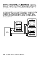
Example 2. Broken Loop (Cable Removed):  

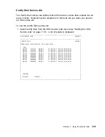
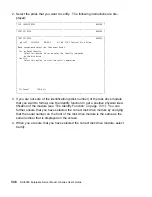
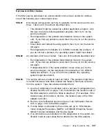
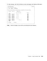
Each disk drive module normally

communicates with the adapter through one data path. Because data can pass
around the loop in either direction, however, the adapter automatically reconfigures
the loop to enable communication to continue to each disk drive if the loop becomes
broken.

In the following diagram, eight disk drive modules should be connected to connectors
A1 and A2 of the SSA adapter. However, the loop is broken because the SSA cable
has been disconnected from connector A2. Four disk drive modules are connected
to connectors B1 and B2 of the same SSA adapter.

Although the broken loop is reported as an error, all the disk drive modules can still
communicate with the using system. The eight disk drive modules can communicate
through connector A1 of the SSA adapter . The five disk drive modules can commu-
nicate through connectors B1 and B2 of the same SSA adapter (normal loop).

7-50

RS/6000 Enterprise Server Model H Series User's Guide 


Содержание H SERIES RS/6000

Страница 1: ...RS 6000 Enterprise Server Model H Series IBM User s Guide SA38 0546 01...

Страница 2: ...d or the program s described in this publication at any time without notice It is possible that this publication may contain reference to or information about products machines and programs programmin...

Страница 3: ...es xi Electrical Safety xi Laser Safety Information xiii Environmental Notices xv Product Recycling and Disposal xv Battery Return Program xv Environmental Design xv About This Book xvii ISO 9000 xvii...

Страница 4: ...gnostics 6 1 Diagnostic Sources 6 1 Standalone and Online Diagnostics Operating Considerations 6 1 Online Diagnostics Modes of Operation 6 9 Standalone Diagnostic Operation 6 12 Location Codes 6 13 Ph...

Страница 5: ...riodic Diagnostics Service Aid 7 19 SCSI Bus Analyzer Task 7 19 SCSI Tape Utilities Service Aid 7 21 Service Hints Service Aid 7 21 Update System or Service Processor Flash Service Aid 7 22 Display Fi...

Страница 6: ...ion Numbers A 1 Device Records A 2 Appendix B Service Processor Setup and Test B 1 Testing the Setup B 2 Appendix C Modem Configurations C 1 Sample Modem Configuration Files C 1 Configuration File Sel...

Страница 7: ...connectors or by unauthorized changes or modifications to this equip ment Unauthorized changes or modifications could void the user s authority to operate the equipment This device complies with Part...

Страница 8: ...ied by the manufacturer do not use or contain excessive voltages An excessive voltage is one which exceeds 70 7 V peak ac or 120 V dc They inter face with this equipment using Safe Extra Low Voltages...

Страница 9: ...is used in a domestic environment radio disturbance may arise When such trouble occurs the user may be required to take corrective actions Electromagnetic Interference EMI Statement Taiwan The followi...

Страница 10: ...dem EMVG Ger te d rfen an Orten f r die sie nicht ausreichend entst rt sind nur mit besonderer Genehmigung des Bundesministers f r Post und Telekommunikation oder des Bundesamtes f r Post und Telekom...

Страница 11: ...Before installing or removing signal cables ensure that the power cables for the system unit and all attached devices are unplugged When adding or removing any additional devices to or from the syste...

Страница 12: ...able from the electrical outlet before relocating the system CAUTION This unit has more than one power supply cord To reduce the risk of elec trical shock disconnect two power supply cords before serv...

Страница 13: ...to the requirements of the International Electrotechnical Commission IEC 825 1st edition 1984 and CENELEC EN 60 825 1991 for Class 1 laser products CAUTION A class 3 laser is contained in the device D...

Страница 14: ...xiv RS 6000 Enterprise Server Model H Series User s Guide...

Страница 15: ...e United States IBM has established a collection process for reuse recycling or proper disposal of used IBM batteries and battery packs For information on proper disposal of the batteries in this unit...

Страница 16: ...xvi RS 6000 Enterprise Server Model H Series User s Guide...

Страница 17: ...g the 7015 Model R00 Rack which the RS 6000 Enterprise Server Model H Series may be installed in The 7014 Model S00 Rack Installation and Service Guide contains information regarding the 7014 Model S0...

Страница 18: ...emark of the International Business Machines Corpo ration PowerPC is a trademark of the International Business Machines Corporation Velcro is a trademark of Velcro Industries xviii RS 6000 Enterprise...

Страница 19: ...ers ISA as an addi tional bus architecture to accommodate businesses that already have invested in ISA and ISA based devices This book helps you use the system install and remove some options configur...

Страница 20: ...pable disk drives One 1 44MB diskette drive One CD ROM drive One additional media device may be a tape drive CD ROM drive or a non hot swappable disk drive Two power supplies which provide redundant p...

Страница 21: ...This means that the equipment and the workplace should be arranged to suit your individual needs and the kind of work you do This web site gives ergonomic guidelines to help you understand the ergonom...

Страница 22: ...does not come on and there is no indication of power when you press the Power On button ensure that the power cord located at the back of the system unit is plugged into a grounded electrical outlet I...

Страница 23: ...on the shutdown procedure for your operating system see your operating system documentation 1 Before stopping the system unit you must first perform a shutdown procedure of the operating system to pre...

Страница 24: ...Display system messages 1 4 3 2 During power on self test POST four characters display indicating the progress of the testing If an error is detected that requires attention the system unit halts and...

Страница 25: ...8 9 6 5 4 Pg Dn End Enter 3 2 1 Ins Del 0 1 2 3 4 5 6 7 9 0 _ Backspace Tab Q W E R Y U I T O P Caps Lock A S D F G H J K L Enter Shift Z X C V B N M Shift Ctrl Alt 8 Alt Ctrl Num Lock Caps Lock Scro...

Страница 26: ...legs The legs snap into position To decrease the tilt of the keyboard rotate the keyboard legs until they snap into the bottom of the keyboard case The keyboard cable plugs into the keyboard connecto...

Страница 27: ...orm such functions as positioning a cursor selecting items from a menu or moving around in your document much easier and faster than if you used only the keyboard The cursor moves exactly as you move...

Страница 28: ...the mouse connector at the rear of the system unit Handling the Mouse Correctly For best operation handle the mouse with care Incorrect handling can damage the mouse Do not Operate the mouse on cloth...

Страница 29: ...erior of the mouse by the ball The surface you use should be free from spills dirt dust lint wax eraser dust and other foreign matter Rough surfaces can also cause the pads located on the bottom of th...

Страница 30: ...irty wash it in warm soapy water Rinse and wipe the ball with a lint free cloth until dry 5 Inspect the ball cavity in the mouse for foreign materials If there are any foreign materials remove them 6...

Страница 31: ...ding to its specified capacity Write Protecting 3 5 Inch Diskettes Write protecting diskettes is necessary so that important information is not acci dentally lost When diskettes are write protected yo...

Страница 32: ...e insert the diskette in the diskette drive with the labeled metal shutter first Push the diskette into the drive until you hear a click The click indicates that the diskette is securely in position i...

Страница 33: ...Unload Button Status Light Volume Control Head Phone Jack When the CD ROM is set to On the status light indicates one of several conditions The following are status light states and the respective co...

Страница 34: ...omes out and then remove the disc Cleaning the CD ROM Drive This CD ROM drive has an internal head cleaning mechanism and therefore does not require an external cleaning device The internal cleaning m...

Страница 35: ...for the location of the emergency eject hole 2 Push the tool in until you feel resistance 3 Maintain a small amount of pressure on the rod while pulling on the tray with your fingernail 4 Pull the tra...

Страница 36: ...each bank identify the PCI Bus indicator and PCI Slot address for the SCSI adapter attached to each bank See AIX and Physical Location Code Reference Table Model 50 on page 6 18 or AIX and Physical Lo...

Страница 37: ...ap Disk Drive D1 Hotswap Disk Drive C2 Hotswap Disk Drive D2 Hotswap Disk Drive C3 Hotswap Disk Drive D3 Hotswap Disk Drive C4 Hotswap Disk Drive D4 Hotswap Disk Drive C5 Hotswap Disk Drive D5 Hotswap...

Страница 38: ...ly Handle the drive by the edges and never touch any exposed circuitry Prevent others from touching the drive Store the hot swap disk drive in a protective container such as an instrument case or in a...

Страница 39: ...status LEDs and spin down button Amber Green Spin Down Button Status LEDs LED or Button Status Definition Amber On Drive spinning Off Drive not spinning Green On Power On Off Power Off Blinking Power...

Страница 40: ...LED Status Definition Power On Power On Off Power Off Ready On Both SSA connections good and drive is ready Blinking Only one SSA connection good Flickering Drive is executing a command Check On Disk...

Страница 41: ...when server power is on and the Service Processor has detected a server problem such as loss of surveillance During the first power up i e power cord is plugged into the outlet Service Processor menus...

Страница 42: ...Boot Y3 Power on System Y3 Power off System Y2 Read NVRAM Y2 Reset Service Processor Y2 Setup Reboot Restart Policy Y2 Y3 Start Talk Mode Y2 Enable Disable Console Mirroring Y2 Y1 Select Modem Line S...

Страница 43: ...SCII terminal to either serial port Because the presence of the ASCII terminal cannot be con firmed by the Service Processor you must press a key on the ASCII terminal to confirm its presence Next the...

Страница 44: ...L USER MENU 1 Power On System 2 Read VPD 3 Read Progress Indicators from Last System Boot 4 Read Service Processor Error Logs 5 Read System POST Errors 6 View System Environmental Conditions 99 Exit f...

Страница 45: ...ed Universal Time CUT a k a Greenwich Mean Time GMT AIX error logs have more information available and are able to time stamp with local time See 3 33 for an example of the error log Read System POST...

Страница 46: ...rver during setup You need the firmware version for reference when you either update or repair the functions of your service processor The System Name an optional field is the name your server reports...

Страница 47: ...ly Service Processor Firmware EPROM 1997 915 FLASH 1997 512 Copyright 1997 IBM Corporation SYSTEM NAME MAIN MENU 1 Service Processor Setup Menu 2 System Power Control Menu 3 System Information Menu 4...

Страница 48: ...ing Currently Disabled 4 Start Talk Mode 5 OS Surveillance Setup Menu 6 Reset Service Processor 7 Reprogram Service Processor Flash EPROM 98 Return to Previous Menu 99 Exit from Menus Note Unless othe...

Страница 49: ...rd to access AIX If the error threshold is reached by someone entering passwords remotely the Service Processor disconnects the modem to prevent potential security attacks on the server by unauthorize...

Страница 50: ...sion only For more information see Console Mirroring on page 3 30 Start Talk Mode In a console mirroring session it is useful for those that are monitoring the session to be able to communicate with e...

Страница 51: ...rvice Processor Reprogram Service Processor Flash EPROM This is an automatic process An update diskette can be acquired from the RS 6000 Support page on the Internet or from your service team The Inte...

Страница 52: ...ervers that require automatic power on after a power failure Ring Indicator Power On Menu Ring Indicate Power On is an alternate method of dialing in without establishing a Service Processor session I...

Страница 53: ...em Boot 3 Read Progress Indicators from Last System Boot 4 Read Service Processor Error Logs 5 Read System POST Errors 6 Read NVRAM 7 View System Environmental Conditions 98 Return to Previous Menu 99...

Страница 54: ...CUT a k a Greenwich Mean Time GMT AIX error logs have more information available and are able to time stamp with local time See 3 33 for an example of the error log Read System POST Errors Selecting t...

Страница 55: ...tolerance 12 Volts A low 12 voltage reading detected 12 Volts A high 12 voltage reading detected Press Return to Continue Language Selection Menu LANGUAGE SELECTION MENU 1 English 2 Francais 3 Deutsc...

Страница 56: ...3 21 Ring Indicate Power On Menu see 3 12 Modem Configuration Menu The first two lines of the Modem Configuration Menu are status lines showing the current selections Selections are made in the two se...

Страница 57: ...z_sp 7 modem_z _sp 8 none 9 Save configuration to NVRAM and Configure modem 98 Return to Previous Menu Serial Port Selection Menu Serial Port Selection Menu 1 Serial Port 1 Call Out Currently Disabled...

Страница 58: ...elephone numbers for Service Center Telephone Number The telephone number of the maintenance provider s computer Customer Administration Center Telephone Number The telephone number of the local syste...

Страница 59: ...Customer Administration Center Telephone Number is the number of the System Administration Center computer catcher that receives problem calls from servers Contact your system administrator for the co...

Страница 60: ...ected The service or administration center represen tatives need this number to make direct contact with your server for problem investigation This is also referred to as the call in phone number Call...

Страница 61: ...r messages Customer Account Setup Menu Customer Account Setup Menu 1 Customer Account Number Currently Unassigned 2 Customer RETAIN Login UserID Currently Unassigned 3 Customer RETAIN Login Password C...

Страница 62: ...pts to reboot the number of times specified Entry values equal to or greater than 0 are valid Only successive failed reboots attempts count not reboots that occur after a restart attempt At restart th...

Страница 63: ...ocessor to call out and report the event This item is valuable if the number of these events becomes excessive signalling a bigger problem Service Processor Functions and Features The following sectio...

Страница 64: ...all Out enable disable Flash Gold Recovery block Update Flash Composite block Update System Name Modem Configuration Remote User Functions Call Out Call Home Reporting Boot failure OS Termination Surv...

Страница 65: ...own t command on servers using AIX Working in conjunction with AIX the Service Processor in your server can operate a timer much like the wake up timer on your clock radio You can set the timer so tha...

Страница 66: ...onitor operating system activity see the SERVICE PROCESSOR SETUP MENU item Set Surveillance Parameters If OS activity stops the Service Processor can initiate a reboot restart process based on the set...

Страница 67: ...r surveillance and either 1 The Use OS Defined restart policy is set to NO OR 2 The Use OS Defined restart policy is set to YES and the operating system has NO automatic restart policy Refer to Servic...

Страница 68: ...machine powered on logs an error and offers menus to the user If Call out is enabled the Service Processor calls to report the failure and dis plays the operating system surveillance failure code on t...

Страница 69: ...tem surveillance failure if supported by Operating System Critical environmental failures Restarts To enable the call out feature you need to do the following Have a modem connected to serial port 1 o...

Страница 70: ...in which console mirroring can be invoked 1 Remote session first then local session added a Remote session already in progress b Remote user uses the Service Processor menus to enable console mirrori...

Страница 71: ...fter initiation the processes are identical and automatic There are two areas in each firmware module that may need updating 1 The gold code or base code or EPROM area 2 The custom or main program or...

Страница 72: ...om the Service Aids Note This service aid is only supported for Online Diagnostics This service aid allows you to update the system or service processor flash Additional update and recovery instructio...

Страница 73: ...e filename is the name of the flash update image During the process the server powers down and reboots The process is complete when the login prompt reappears Service Processor Logs Service Processor...

Страница 74: ...ad System POST Errors Version Severity Disposition Initiator Event being reported Extended Error Log Data xC2 x x84 x 9 x x x x x2 x x x x x x72 x74 x63 x x x x x x x x x x28 x 3 x x 5 x x 1 x x x x x...

Страница 75: ...an ASCII display as your system console see Text Based System Management Services on page 4 24 Graphical System Management Services To start the Open Firmware command line or graphical System Manageme...

Страница 76: ...d happen if the battery had been removed In order to recreate this value issue the bootlist command under AIX with the appropriate parameters as to the location of the operating system in a particular...

Страница 77: ...rror log and update your system firmware Exit Returns you to the previous screen To select an icon move the cursor with the arrow keys to choose which icon is high lighted then press the Enter key You...

Страница 78: ...is icon makes it possible for you to view information about the setup of your system unit A list similar to the following appears when you select the Config icon 4 4 RS 6000 Enterprise Server Model H...

Страница 79: ...down arrow key or Page Down key displays the next configuration screen which lists your computer s firmware version the date of its development and the firmware part number Chapter 4 System Management...

Страница 80: ...value issue the bootlist command under AIX with the appropriate parameters as to the location of the operating system in a particular hard disk See the explanation of the bootlist command in your AIX...

Страница 81: ...lect Software option if supported by the operating system shows the names of the operating system installed This option may not be supported by all operating systems Chapter 4 System Management Servic...

Страница 82: ...all operating systems The Install From option produces a list of devices for example the CD ROM where the operating system is installed from You select one of the devices and the system searches the...

Страница 83: ...fault boot sequence is The primary diskette drive CD ROM drive For CD ROM boot go to the Install From icon and then select CD ROM Drive as a boot device Tape id 5 slot 1 Hard disk drive id 6 Slot 1 Ne...

Страница 84: ...ribes the choices available on this screen Password Enables you to set password protection for turning on the computer and for using system administration tools Spin Up Enables you to change the spin...

Страница 85: ...pdate the firmware programs on your computer Console If you have more than one display attached to your system unit or if you have an ASCII terminal attached to your system unit in addition to a keybo...

Страница 86: ...finished you are required to type the password again for verification If you make a mistake press the Esc key and start again After you have entered and verified the password the power on password ico...

Страница 87: ...leged Access Password The privileged access password protects against the unauthorized starting of the system programs When you select the Entry icon a screen with eight empty boxes appears Type your...

Страница 88: ...o indicate that your computer now requires the password you just entered before running system programs Note If you forget the power on password the battery must be removed for longer than 30 seconds...

Страница 89: ...your system Spin up delay values can be entered manually or a default setting can be used All values are measured in seconds The default is two seconds After you have entered the new Spin up delay val...

Страница 90: ...rrors your computer has encountered during operations Selecting the Clear icon erases the entries in this log For an explanation of errors in the system error log see your System Service Guide 4 16 RS...

Страница 91: ...RIPL Selecting the Remote Initial Program Load RIPL icon gives you access to the fol lowing selections Chapter 4 System Management Services 4 17...

Страница 92: ...le 129 132 4 20 may need to be entered as 123 132 004 020 If any of the addresses is incomplete or contains a number other than 0 to 255 an error message is displayed when you select the Save icon To...

Страница 93: ...cified address is valid by sending a test transmission to that address After choosing the Ping option you may be asked to indicate which communications adapter should be used to send the test transmis...

Страница 94: ...r to select the adapter then highlight the OK icon and press the Enter key The next screen allows you to select the configuration of the adapter you have just chosen or allow the system to select the...

Страница 95: ...w keys to high light the entry then use the spacebar to scroll through the available IDs After you have entered the new address use the arrow keys to highlight the Save icon and press the Enter key At...

Страница 96: ...ro When prompted insert the firmware update diskette containing the new firmware image ATTENTION While the new firmware image is being copied into your system unit you must not turn off the system uni...

Страница 97: ...your system unit is turned off 4 Insert the firmware recovery diskette into your system unit 5 Turn on your system unit 6 When the keyboard indicator appears press the 1 key if the system console is...

Страница 98: ...ut your system unit and to perform such tasks as setting passwords and changing device configurations After the text based System Management Services starts the following screen appears System Managem...

Страница 99: ...to the following is displayed Device PowerPC 6 4 L2 Cache 512K Memory slotA 8MB slotB 8MB LPT addr 3BC COM addr 3F8 COM addr 2F8 Audio Keyboard Mouse Diskette addr 3F Integrated Ethernet addr 8 5AF67...

Страница 100: ...rticular hard disk Please see the explanation of the bootlist command in your AIX documentation for more information The Software Default option lets you select the default operating system to start t...

Страница 101: ...on enables you to view and change the custom boot list which is the sequence of devices read at startup time Select Boot Devices 1 Display Current Settings 2 Restore Default Settings 3 Configure 1st B...

Страница 102: ...t Sequence 1 Diskette 2 Ethernet Integrated 3 SCSI CD ROM id 3 slot 1 4 SCSI 5 MB Hard Disk id 6 slot 1 5 SCSI 5 MB Hard Disk id 5 slot 5 X Exit Selecting any of the Configure Boot Device options disp...

Страница 103: ...up 5 Change SCSI id 6 Update System Firmware 7 Update Service Processor 8 Select Console X Exit Set Password and Unattended Start Mode Entering this selection permits access to the following options P...

Страница 104: ...d Access Password The privileged access password protects against the unauthorized starting of the system programs If you previously set a privileged access password and want to remove it select Remov...

Страница 105: ...P Address 4 Subnet Mask X Exit Selecting the Adapter Parameters option allows you to view an adapter s hardware address as well as configure network adapters that require setup Adapter Parameters Devi...

Страница 106: ...a tion menus 3Com Etherlink Fast XL 1 Media Type Auto 2 Full Duplex Auto X Exit Selecting the Media Type option allows you the change the media employed by the Ethernet adapter MEDIA TYPE 1 1 BaseT 2...

Страница 107: ...he last option available from the Network Parameters Menu allows you to test a connection to a remote system unit After selecting the Ping option you must choose which adapter communicates with the re...

Страница 108: ...e system Ping 1 Client IP Address 129 132 4 2 2 Server IP Address 129 132 4 1 3 Gateway IP Address 129 132 4 3 4 Subnet Mask 255 255 255 E Execute X Exit Hard Disk Spin Up Delay Selecting this utility...

Страница 109: ...is displayed when you select this option You can view or clear your computer s error log Error Log Date Time ErrorCode Location Entry 1 96 4 1 12 13 22 25A8 11 Entry 2 no error logged C Clear Error L...

Страница 110: ...ontinue Press Y Yes N No System Firmware Recovery If a troubleshooting procedure has indicated that the firmware information in your system unit has been corrupted then you must perform a firmware rec...

Страница 111: ...f no console is selected within two minutes the console defaults to Serial Port 2 Select Language This option allows you to change the language used by the text based System Man agement Services scree...

Страница 112: ...tandard 1275 The Open Firmware command line is used to set up adapters that are not configurable with the System Management Services Your adapter documentation directs you to use this option if it is...

Страница 113: ...o install another If you have several internal options to install these instructions enable you to add them all at one time Before you start be sure you are familiar with the safety and handling guide...

Страница 114: ...possible disconnect all power cables from the existing system before you add a device Use one hand when possible to connect or disconnect signal cables to prevent a possible shock from touching two s...

Страница 115: ...from the antistatic bag until you are ready to install the device in the system unit With the device still in its antistatic bag touch it to a metal frame of the system Grasp cards and boards by the e...

Страница 116: ...s special design gives you the flexibility to use up to twelve 3 5 inch disk drives either SCSI or SSA in banks C and D To install SSA drives in banks C and D however a SCSI disk drive must be install...

Страница 117: ...ves for removal 1 Touch the static protective bag containing the drive to any unpainted metal surface on the system then remove the drive from the bag Static Devices 2 Check the instructions that came...

Страница 118: ...information regarding the operation of the hot swap disk drives see the installation and users guide that came with the drives Remember that each 1 6 inch disk drive takes two bays To run SSA drives...

Страница 119: ...cover to the drawer and remove the disk drive cover from the drawer storing it in a safe place 3 Each hot swap disk drive you plan to install must have the hot swap disk drive carrier attached Attent...

Страница 120: ...ntion Attaching SCSI address jumpers on the hot swap disk drive rather than using the automatic ID furnished by the backplane is not advised Attaching jumpers can cause service problems multiple drive...

Страница 121: ...he raised guides on the left of the bay d Slide the carrier into the bay gently to keep from damaging the hot swap disk drive Slide the carrier to the rear of the bay until it is seated into the con n...

Страница 122: ...lluminates SCSI Disk Drives The following table explains the meaning of the green and amber status LEDs and spin down button on a SCSI disk drive Status LEDs LED or Button Status Definition Amber On D...

Страница 123: ...nection good Flickering Drive is executing a command Check On Disk drive failure Self test running Drive in service mode Blinking Disk drive selected 6 Go to Appendix A on page A 1 to record the drive...

Страница 124: ...a hot swap disk drive when the CPU Drawer power is off steps 3 on page 5 13 and 4 on page 5 14 do not apply Attention Follow all procedures for ESD sensitive parts while performing these pro cedures...

Страница 125: ...safe place Attention Physically removing a hot swap drive from the CPU Drawer before it has been removed from the system configuration may cause unrecoverable data corruption 3 Verify that the device...

Страница 126: ...n SCSI Disk Drives SSA Disk Drives Attention SSA backplanes must be fully populated Each backplane connector must have a disk drive or a blank carrier installed at all times If you remove a disk drive...

Страница 127: ...handling 7 If you are removing another disk drive return to Installing Disk Drives into the Hot Swap Bays on page 5 6 8 If you are installing another disk drive or carrier blank in bank C or D go to R...

Страница 128: ...5 16 RS 6000 Enterprise Server Model H Series User s Guide...

Страница 129: ...the diagnostics 1 When diagnostics are installed the device support for some devices may not get installed If this is the case that device does not appear in the diagnostic test list when running disk...

Страница 130: ...s again Running Standalone Diagnostics Consider the following when you run Standalone Diagnostics The diagnostic disc must remain in the CD ROM drive for the entire time that diagnostics are executing...

Страница 131: ...un diagnostics using a TTY type terminal as the console display See the operator manual for your type of tty terminal to find the key sequences you need to respond to the diagnostics For the 3151 refe...

Страница 132: ...erminal and set your attributes accordingly Generated Code Set ASCII Screen Normal Normal Uses the EIA 232 interface pro tocol Row and filemn 24 x 80 24 x 80 Uses the EIA 232 interface pro tocol Scrol...

Страница 133: ...he page Forcing insert Off Off Tab Field Field Field The column tab stops are ignored and the tab operation depends on the field attribute character positions Trace All Both inbound data data to the s...

Страница 134: ...bit and is used together with the word length attribute to form the 8 bit data word byte Stop bit 1 1 1 Places a bit after a data word byte Turnaround character CR CR CR Selects the carriage return C...

Страница 135: ...ew line New line The cursor moves to the next line when the Return key is pressed New line CR CR CR The Return key generates the car riage return CR and the line feed LF characters The line turnaround...

Страница 136: ...ttings Description Line speed 9600 9600 9600 Uses 19200 or 9600 bps bits per second line speed to communicate with the system unit Word length bits 8 8 8 Selects eight bits as a data word length byte...

Страница 137: ...owing steps 1 Stop all programs including the AIX operating system get help if needed 2 Turn the power off 3 Remove all tapes diskettes and CD ROMs 4 Turn the power on a When or after the diskette ind...

Страница 138: ...t mode The share test level tests a resource while the resource is being shared by pro grams running in the normal operation This testing is mostly limited to normal commands that test for the presenc...

Страница 139: ...he resources available to check All of the system resources except the SCSI adapters memory processor and the disk drive used for paging can be checked Error log analysis is done in maintenance mode w...

Страница 140: ...ve and the SCSI controller that controls it cannot be tested by the Standalone Diagnostics Running the Standalone Diagnostics To run Standalone Diagnostics in service mode take the following steps 1 V...

Страница 141: ...te physical package and it plugs into or is connected to the parent For example P1 C1 is a CPU card C1 plugged into a planar P1 or P1 M1 is a memory card M1 plugged into a planar P1 The slash separato...

Страница 142: ...ded for use as an abbreviation of the location code in cases where 1 Based on the device structure the abbreviated sub location code conveys the same information in a more concise form than an additio...

Страница 143: ...mbers This allows the location code to uniquely identify multiple adapters on individual PCI cards For pluggable ISA adapters CD is equal to the order the ISA cards defined configured either by SMIT o...

Страница 144: ...evice Control Unit Address of the SCSI Device Connector ID devfunc Number Adapter Number or Physical Location Bus Type or PCI Parent Bus Where AB CD EF are the same as non SCSI devices G defines the c...

Страница 145: ...o 10 7F Any PCI card in slot 5 Model 50 only 30 60 to 30 67 Any PCI card in slot 6 Model 50 only 40 58 to 40 5F Any PCI card in slot 5 Model 70 only 40 60 to 40 67 Any PCI card in slot 6 Model 70 only...

Страница 146: ...AIX and Physical Location Code Reference Table Model 50 6 18 RS 6000 Enterprise Server Model H Series User s Guide...

Страница 147: ...Chapter 6 Using the Online and Standalone Diagnostics 6 19...

Страница 148: ...13L 13H 15L 15H Memory Card 2 00 00 P1 M2 Processor Con nector J13 Memory Card 2 modules 1 thru 16 00 00 P1 M2 1 through P1 M2 16 Memory Card Sockets J1 J2 J3 J4 J5 J6 J7 J8 J9 J10 J11 J12 J13 J14 J15...

Страница 149: ...20 58 to 20 5F P2 I1 I O board Con nector J1 Host Bridge ID01 Device 01 Card in PCI Slot 2P 20 60 to 20 67 P2 I2 I O board Con nector J2 Host Bridge ID01 Device 02 Card in PCI Slot 3P 10 68 to 10 6F P...

Страница 150: ...con nected to SCSI Port 1 P2 Z1 10 60 00 15 0 P2 Z1 B2 Primary SCSI Bus ID 15 SCSI Backplane C When con nected to SCSI Port 2 P2 Z2 30 58 00 15 0 P2 Z2 B2 Secondary SCSI Bus ID 15 DASD in Bays C1 thro...

Страница 151: ...r s slot and G identifies the SCSI Bus ID 8 through 13 P2 In Z1 B2 1 through B2 6 Bus ID 8 through 13 SCSI Backplane E When con nected to PCI adapter in slot P2 In AB CD 00 15 0 Where AB CD identifies...

Страница 152: ...nector J22A Operator Panel Connector P2 L1 I O board Con nector J22A Power Supply Power Supply 1 V1 PDB connector J1A J1B Power Supply 2 V2 PDB connector J2A J2B Note The SCSI bus IDs are the recomme...

Страница 153: ...essor Card primary Processor Card P2 L1 P2 X4 P2 X4 P2 X2 Memory Card Memory Card Operator Panel Power Distribution Board Power Distribution Board FMC Card 10 60 SCSI Port 1 01 D1 X2 F5 X2 F7 X2 F8 X2...

Страница 154: ...R1 P2 Z2 40 58 to 40 5F 40 60 to 40 67 30 70 to 30 77 30 68 to 30 6F 10 70 to 10 77 10 68 to 10 6F 20 60 to 20 67 20 58 to 20 5F PCI 32 Bit PCI 32 Bit PCI 32 Bit PCI 32 Bit PCI 64 Bit PCI 64 Bit PCI 6...

Страница 155: ...Memory Card 2 00 00 P1 M2 Processor Con nector J3 Memory Card 2 Memory modules 1 thru 16 00 00 P1 M2 1 through P1 M2 16 Memory Card Sockets J1 J2 J3 J4 J5 J6 J7 J8 J9 J10 J11 J12 J13 J14 J15 J16 Exten...

Страница 156: ...d in PCI Slot 2P 20 60 to 20 67 P2 I2 I O Planar Con nector J18 Host Bridge ID01 Device 02 Card in PCI Slot 3P 10 68 to 10 6F P2 I3 I O Planar Con nector J19 Host Bridge ID00 Device 03 Card in PCI Slo...

Страница 157: ...B2 6 Backplane con nector J6 through J11 Slots A through F Primary SCSI Bus ID 8 through 13 DASD in Bays C1 through C6 When con nected to SCSI Port 2 P2 Z2 10 88 00 G 0 Where G identi fies Secondary S...

Страница 158: ...Bays D1 through D6 When con nected to PCI adapter in slot P2 In AB CD 00 G 0 Where AB CD identifies the adapter s slot and G identifies the SCSI Bus ID 8 through 13 P2 In Z1 B2 1 through B2 6 Backplan...

Страница 159: ...nd Control Card Fan Monitor and Control Card X2 I O Planar Con nector J27 Power Supplies Power Supply 1 V1 Power Supply2 V2 Note The SCSI bus IDs are the recommended values Features installed at the m...

Страница 160: ...6 32 RS 6000 Enterprise Server Model H Series User s Guide...

Страница 161: ...Aid 7 14 Display Vital Product Data VPD Service Aid and Display Hardware Vital Product Data Task 7 14 Display Configuration Service Aid and Display Configuration and Resource List Task 7 14 Change Ha...

Страница 162: ...aths 7 28 SSA Service Aids 7 30 The Identify Function 7 31 Starting the SSA Service Aids 7 31 Set Service Mode Service Aid 7 33 Link Verification Service Aid 7 38 Configuration Verification Service Ai...

Страница 163: ...y data and do additional testing Options for the service aids are available when the software package for that option is installed The service aids are selected via the Task Selection Menu Refer to th...

Страница 164: ...eft in tmp to allow for visual comparison All errors are reported Configure Remote Maintenance Policy Service Aid The Remote Maintenance Policy includes modem configurations and phone numbers to use f...

Страница 165: ...dministration Center Phone Number This is the number of the System Administration Center computer the catcher that receives problem calls from systems Contact the system administrator for the correct...

Страница 166: ...e System Administrator Aid This is the name given to the system and is used when reporting problem mes sages Note Knowing the system name aids the support team to quickly identify the location configu...

Страница 167: ...s between heartbeats from the operating system Surveillance Time Delay This is the time to delay in minutes between when the operating system is in control and when to begin operating system surveilla...

Страница 168: ...Reboot Policy When Use the O S Defined Restart Policy is set to No or the operating system restart policy is undefined then the restart policy is determined by the Supple mental Restart Policy Enable...

Страница 169: ...ly from the AIX command line by entering usr lpp diagnostics bin uspchrp a Diagnostic Package Utility Service Aid The Diagnostic Package Utility Service Aid allows the user to perform the following ac...

Страница 170: ...rmat Certify and Erase Disk service aid for each type of hard disk supported and an Optical Disk service aid for supported optical disks Certify Certify reads all of the ID and data fields It checks f...

Страница 171: ...ewly installed drive you can ensure that all blocks on the disk are over written with your pattern if you use the following procedure 1 Format the drive 2 Check the defect map by running the Erase Dis...

Страница 172: ...e for using this service aid requires that both the old and new disks be installed in or attached to the system with unique SCSI addresses This requires that the new disk drive SCSI address must be se...

Страница 173: ...cleaning the disk Format and Certify This service aid is used to format the optical disk and certify it The certification process is drive specific and performs the surface analysis of all user data a...

Страница 174: ...hose resources Use this service aid when you want to look at the VPD for a specific resource This service aid displays information about the installed software and provides the following functions Lis...

Страница 175: ...o add resources back to the resource list Delete Resource from Resource List Task Use this task to delete resources from the resource list Change Configuration Service Aid and Add or Delete Drawer Con...

Страница 176: ...te Only resources that were previously detected by the diagnostics and have not been deleted from the Diagnostic Test List are listed If no resources are available to be deleted then none are listed D...

Страница 177: ...and their ports Lists all SCSI devices on each port Generic Microcode Download Service Aid This service aid provides a means of restoring a diskette or other media and exe cuting a restored program T...

Страница 178: ...ce aid Whenever an ISA adapter is installed this Service Aid must be run and the adapter configured before the adapter can be tested This Service Aid must also be run and the adapter removed whenever...

Страница 179: ...iodic Diagnostics Service Aid This service aid provides a tool for configuring periodic diagnostics and automatic error log analysis A hardware resource can be tested once a day at a user speci fied t...

Страница 180: ...onse back without any errors being detected The service aid transmitted a SCSI inquiry command and did not receive any response or error status back The service aid transmitted a SCSI inquiry command...

Страница 181: ...size of the trace table The names of the data files have the fol lowing format TRACE X DAT where X is a sequential diskette number The complete trace table consists of the sequential concatenation of...

Страница 182: ...image file will be copied in the var file system If there is not enough space in the var file system for the flash update image file an error is reported If this occurs exit the service aid increase...

Страница 183: ...at a selected disk drive Array Controller Microcode Download This selection allows the microcode on the 7135 controller to be updated when required Physical Disk Microcode Download This selection is u...

Страница 184: ...the using system A B C D E F G H Always Always Always P Physical disk drive module L Logical disk drive Adapter position number of the slot 1 through 8 containing the SSA adapter System I O bus identi...

Страница 185: ...rough a link SSA cable to the disk drive modules The path continues through the disk drive modules then returns through another link to a second connector on the SSA adapter The SSA Adapter The system...

Страница 186: ...k drive modules are arranged in a string of 2 to 6 disk drive modules This string has its own two SSA connectors This string is connected through an internal SSA cable to a pair of connectors on the S...

Страница 187: ...but can always be found by the software Service actions are always related to physical disk drives For this reason errors that occur on SSA disk drives are always logged against the physical disk dri...

Страница 188: ...ct which data path is being used If a disk drive module fails or is turned off the loop is broken and one of the data paths to a particular module is no longer available The disk drive modules on the...

Страница 189: ...rive modules in slots 2 and 4 have failed The disk drive module in slot 1 can communicate with the using system only through connector A1 of the SSA adapter The disk drive module in slots 5 and 6 can...

Страница 190: ...Verification This service aid tells you the operational status of an SSA link Configuration Verification This service aid lets you determine the relationship between physical and logical disk drives...

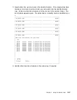
Страница 191: ...ce aids tell you when you can select the identify function Note You cannot use the identify function on a device that is in reserved status Starting the SSA Service Aids To start the SSA service aids...

Страница 192: ...the SSA SERVICE AIDS menu 5 Select the service aid that you require then go to the relevant instructions in this chapter Set Service Mode Service Aid on page 7 33 Link Verification Service Aid on pag...

Страница 193: ...hat passes through it might still be active even though the disk drive module itself might not be working You must put that module into the service mode before you remove it from the SSA link If you q...

Страница 194: ...press Enter Set or Reset Identify Select this option to set or reset the Identify indicator on the disk drive Set or Reset Service Mode Select this option to set or reset Service Mode on the disk driv...

Страница 195: ...ve pdisk8 99999999 4 P 9 1 GB SSA F Physical Disk Drive BOTTOM F3 Cancel F1 Exit Notes a You can select only one disk drive module at a time b If you select the service mode function and the selected...

Страница 196: ...81 SET SERVICE MODE 8 2382 pdisk5 66666666 4 P 9 1 GB SSA F Physical Disk Drive Move cursor onto selection then press Enter Set or Reset Identify Select this option to set or reset the Identify indica...

Страница 197: ...2381 Move cursor onto selection then press Enter TOP pdisk 11111111 4 P 9 1 GB SSA F Physical Disk Drive pdisk1 22222222 4 P 9 1 GB SSA F Physical Disk Drive pdisk2 33333333 4 P 9 1 GB SSA F Physical...

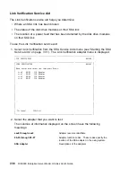
Страница 198: ...he Link Verification adapter menu is displayed SSA SERVICE AIDS 8 238 LINK VERIFICATION 8 2385 Move cursor onto selection then press Enter ssa 3 SSA Adapter ssa1 5 SSA Adapter ssa2 6 SSA Adapter ssa3...

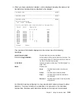
Страница 199: ...rmation displayed on the screen have the following meanings An SSA link must be configured in a loop around which data can travel in either direction The loop is broken if a cable fails or is removed...

Страница 200: ...nt Asterisks indicate an unconfigured device That device might be Another SSA adapter that is in the same using system or in a different using system An SSA device that is in the SSA network but whose...

Страница 201: ...nformation and operational status of the disk drives Note User applications communicate with the hdisks error data is logged against the pdisks To use the Configuration Verification service aid 1 Sele...

Страница 202: ...Status TOP pdisk 22222222 2 A1 5 Good 2 A2 5 Good 3 A1 1 Good 3 A2 Good BOTTOM F3 Cancel F1 Exit If you select a pdisk a list of hdisks is displayed SSA SERVICE AIDS 8 238 CONFIGURATION VERIFICATION 8...

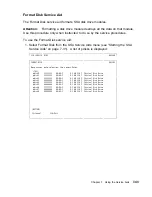
Страница 203: ...DS 8 238 FORMAT DISK 8 2395 Move cursor onto selection then press Enter TOP pdisk 11111111 4 P 9 1 GB SSA F Physical Disk Drive pdisk1 22222222 4 P 9 1 GB SSA F Physical Disk Drive pdisk2 33333333 4 P...

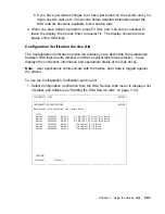
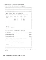
Страница 204: ...THE DISK DRIVE F3 Cancel F1 Exit 3 If you are not sure of the identification pdisk number of the disk drive module that you want to format use the identify function to get a positive physical iden tif...

Страница 205: ...RTIFY DISK 8 24 4 Move cursor onto selection then press Enter TOP pdisk 11111111 4 P 9 1 GB SSA F Physical Disk Drive pdisk1 22222222 4 P 9 1 GB SSA F Physical Disk Drive pdisk2 33333333 4 P 9 1 GB SS...

Страница 206: ...Cancel F1 Exit 3 If you are not sure of the identification pdisk number of the disk drive module that you want to format use the identify function to get a positive physical iden tification of the mod...

Страница 207: ...ervice aid again If diagnostics fail or if the same problem occurs when you try the service aid again run the diagnostics from diskette or CD ROM to isolate the problem If you do not find a problem th...

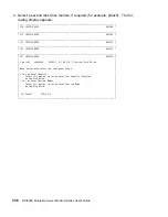
Страница 208: ...ing examples show various loops and the associated information that is displayed by the Link Verification service aid Example 1 Normal Loops In the following diagram eight disk drive modules are conne...

Страница 209: ...Physical Serial Adapter Port A1 A2 B1 B2 Status TOP pdisk nnnnnnnn 7 Good pdisk1 nnnnnnnn 1 6 Good pdisk2 nnnnnnnn 2 5 Good pdisk3 nnnnnnnn 3 4 Good pdisk4 nnnnnnnn 4 3 Good pdisk5 nnnnnnnn 5 2 Good...

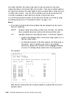
Страница 210: ...connectors A1 and A2 of the SSA adapter However the loop is broken because the SSA cable has been disconnected from connector A2 Four disk drive modules are connected to connectors B1 and B2 of the sa...

Страница 211: ...s Enter Physical Serial Adapter Port A1 A2 B1 B2 Status TOP pdisk nnnnnnnn Good pdisk1 nnnnnnnn 1 Good pdisk2 nnnnnnnn 2 Good pdisk3 nnnnnnnn 3 Good pdisk4 nnnnnnnn 4 Good pdisk5 nnnnnnnn 5 Good pdisk...

Страница 212: ...of the same SSA adapter Although the missing disk drive module is reported as an error all the remaining disk drive modules can still communicate with the using system Two disk drive modules can comm...

Страница 213: ...ss Enter Physical Serial Adapter Port A1 A2 B1 B2 Status TOP pdisk nnnnnnnn Good pdisk1 nnnnnnnn 1 Good pdisk3 nnnnnnnn 4 Good pdisk4 nnnnnnnn 3 Good pdisk5 nnnnnnnn 2 Good pdisk6 nnnnnnnn 1 Good pdis...

Страница 214: ...scribed in Finding the Device When No Service Aids Are Available Finding the Device When No Service Aids Are Available When no service aids are available you must find the device by using the port P a...

Страница 215: ...to check for example ssa0 The response to this command is ucode 8F97 nn name of adapter download False where nn is the adapter code package ID Use the Display or Change Configuration or Vital Product...

Страница 216: ...specific Z2 RAM code load part number Device specific Z3 Electronics card assembly part number Device specific Z4 Disk enclosure date of manufacture The VPD for the SSA Adapter is Part number Adapter...

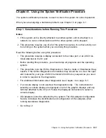
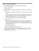
Страница 217: ...g this procedure you should stop all programs and the operating system This procedure runs the Online Diagnostics in Service mode or Standalone Diag nostics If the Online Diagnostics are installed the...

Страница 218: ...Diagnostics from a TTY Terminal on page 6 3 Return to substep 5 when you finish checking the attributes 5 Turn the power on a When the keyboard indicator appears press F5 on the direct attached key bo...

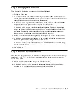
Страница 219: ...e representative they may instruct you to install wrap plugs to better isolate a problem 4 Select the System Verification option on the Diagnostic Mode Selection menu 5 If you want to run a general ch...

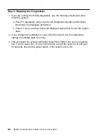
Страница 220: ...and then follow the displayed instructions to shut the system down 2 If you changed any attributes on your ASCII terminal to run the diagnostics change the settings back to normal 3 This completes the...

Страница 221: ...I terminal to find the key sequences you need to respond to the diagnostic programs The diagnostics can use a display connected to the video port or a ASCII ter minal attached to a serial port This pr...

Страница 222: ...tic tests can be run on many resources while the operating system is running However more extensive problem isolation is obtained by running Online Diagnostics in Service mode Do you want to run the O...

Страница 223: ...ng system 2 After the operating system is stopped power off the system unit 3 Go to Step 6 YES Go to Step 9 Step 6 This step loads Online Diagnostics in service mode If you are unable to load the diag...

Страница 224: ...cs loaded correctly Press the Enter key Is the Function Selection menu displayed NO Go to Step 10 YES Go to Step 11 Symptom Action Display problem Go to Step 8 All other symptoms Go to Problem Determi...

Страница 225: ...oblem to the service organization 102 key keyboard Identify by the type of Enter key used The Enter key extends into two hori zontal rows of keys Record error code M0KBD002 and report the problem to t...

Страница 226: ...Resource menu is displayed Follow the displayed instructions until either the Diagnostic Mode Selection menu or an SRN is displayed If the Diagnostic Mode Selection menu is dis played select Problem D...

Страница 227: ...A adapter Configuration Service Aid allows the identification and configuration of ISA adapters for Stand alone Diagnostics ISA adapters must be identified and configured before they can be tested Sel...

Страница 228: ...aults of the diagnostic programs The ASCII terminal must be attached to serial port 1 on the system unit Are you going to load Standalone Diagnostics and run them from a ASCII ter minal NO Go to Step...

Страница 229: ...attached keyboard or 5 on the ASCII keyboard to indicate that diagnostics are to be loaded 4 Enter requested passwords 5 Follow instructions to select a console Did the Diagnostics Operating Instructi...

Страница 230: ...FRUs are needed to restore the system to correct operation Step 1 Considerations before Running This Procedure The diagnostics can use a display connected to the video port or a ASCII terminal attach...

Страница 231: ...he diagnostics load NO Go to Step 5 YES Go to Step 6 Step 4 This step attempts to load the Standalone diagnostics 1 Turn the power to off 2 Turn the power to on 3 Insert the diagnostic CD ROM into the...

Страница 232: ...NO beep heard from the system unit during the IPL sequence Record error code M0SPK001 The system stops with the Diagnostic Operating Instructions displayed Go to Step 6 The diskette LED is blinking r...

Страница 233: ...may be faulty 1 Check the SMS error log for any errors To check the error log Choose tools Choose error log If an error is logged check the time stamp If the error was logged during the current boot a...

Страница 234: ...w of keys Record error code M0KBD001 and report the problem to the service organization 102 key keyboard Identify by the type of Enter key used The Enter key extends into two hori zontal rows of keys...

Страница 235: ...rom the SSA adapter They check whether the disk drive module is working correctly The POSTs also help verify a repair after a FRU has been exchanged There are two power on self tests POST 1 and POST 2...

Страница 236: ...rdware is correct the POST sets the ROS level to zero puts the identification of the SSA adapter into POS 0 1 and puts error data into the adapter status register To recover from this type of error mi...

Страница 237: ...and retain the following information The server s identification numbers are located on the front cover and on the rear of the server Product Name RS 6000 Enterprise Server Model H Series CPU Type Sp...

Страница 238: ...J5 J6 32MB 128MB 256MB Memory J7 J8 32MB 128MB 256MB Memory J9 J10 32MB 128MB 256MB Memory J11 J12 32MB 128MB 256MB Memory J13 J14 32MB 128MB 256MB Memory J15 J16 32MB 128MB 256MB Mouse Connector IBM...

Страница 239: ...led at the manufacturing site correspond to these IDs Field installations may not comply with these recommendations B2 optional SCSI boot disk drive behind op panel display C2 hot swappable disk drive...

Страница 240: ...Bay B1 Non SCSI 3 5 Inch 1 44MB Diskette Drive Inte grated Bay B2 6 Optional Disk Drive non hot swappable boot drive Bank C Bay 1 8 Bank C Bay 2 9 Bank C Bay 3 10 Bank C Bay 4 11 Bank C Bay 5 12 Bank...

Страница 241: ...3 on page 3 1 5 Set the System Name Privileged User Menus on page 3 6 6 Enable Surveillance see 3 8 and Service Processor Functions and Features on page 3 23 7 Configure Call In Call Out see Call in...

Страница 242: ...wer y when asked if you wish to continue powering on the system 4 After the system firmware and operating system have initialized the server the login prompt appears at your remote terminal if you set...

Страница 243: ...d error condition for the purposes of this test 4 After a few moments a message appears regarding an illegal entry Press Enter to clear the message and return to the main menu 5 When your telephone ri...

Страница 244: ...configured none are listed If you wish to configure serial ports that are not listed continue with the remaining steps 3 Identify the serial port s with the modem s 4 Enter smit tty 5 Select add tty...

Страница 245: ...iles are in your RS 6000 Enterprise Server Model H Series firmware in the usr share modems subdirectory if your server is using AIX with the following names A listing of each specific file is included...

Страница 246: ...attach to the PTSN connector Also see the note on page C 3 If No continue with step 3 3 Does your modem respond to the extended command set prefixed with If Yes go to step 5 If No continue with step...

Страница 247: ...1 You should edit out these commands from the modem configuration file if yours is such a modem See your modem manual for more information Note Some modems such as IBM 7857 017 are not designed for th...

Страница 248: ...dems modem_f cfg as a model to modify 1 Find the necessary command in your modem manual 2 Copy usr share modems modem_f cfg to a new file with a different name for example modem_fx cfg 3 In the new fi...

Страница 249: ...terrupt only on the first ring signal they receive AT T DataPort 2001 is an example of such a modem The Service Processor uses the ring interrupt request to count the number of rings when Ring Indicat...

Страница 250: ...y that the modem is communicating and to assure it has been initialized recently Another strategy particularly if your system is difficult to access physically is to protect it with an Uninterruptable...

Страница 251: ...his information The Dn command appears in three places each in three of the sample modem configuration files1 2 Will the server s modem disconnect when the power drops You can make this observation at...

Страница 252: ...y console to manifest the modem s response to DTR transitions If a local ASCII terminal or a graphics console is to be a permanent part of your server then make one of them the primary console Your re...

Страница 253: ...lt settings except switches 11 and 12 These must be to UP AT responses and DOWN Asynchronous operation respectively ICDelay 1 DefaultTO 1 CallDelay 12 N Call Out phone number R Return phone number PRO...

Страница 254: ...ory defaults Reliable mode Echo off ignore r or OK r n timeout 2 Ignore modem response send AT E12 E14 r Disable pacing Disable data compression expect r or OK r n timeout 2 Confirm commands successfu...

Страница 255: ...nse send AT E12 E14 r Disable pacing Disable data compression expect r or OK r n timeout 2 Confirm successful command send AT SF1 S S9 1 r DSR independent of CD Force DSR on CD respond time 1 ms expec...

Страница 256: ...hedule Contract with IBM Corp ICDelay 1 DefaultTO 1 CallDelay 12 N Call Out phone number R Return phone number PROGRAMMING NOTE No blanks between double quote marks condout send AT F E E r Reset to fa...

Страница 257: ...tible messages Answer on 2nd ring expect r timeout 2 Confirm commands successful done waitcall ignore 2 r timeout 1 Ignore first ring expect 2 r timeout 1 Pick up second ring or timeout Expect a conne...

Страница 258: ...S r Numeric response code AT compatible messages Auto Answer disabled expect r timeout 2 Confirm commands successful done error Handle unexpected modem responses expect 8 r or 7 r or 4 r or 3 r delay...

Страница 259: ...it Escape to command mode S 2 Answer on second ring H Hang up T Tone mode When used as T r it is a no op to maintain program synchronization when modem may will echo the commands N Call Out phone numb...

Страница 260: ...1 Pick up second ring or timeout Expect a connection response expect 16 r or 15 r or 14 r or 12 r or 1 r or 5 r or 1 r timeout 6 done page send ATDT N R r N pager call center number Add enough commas...

Страница 261: ...it Escape to command mode S 2 Answer on second ring H Hang up X Limit modem response codes T Tone mode When used as T r it is a no op to maintain program synchronization when modem may will echo the c...

Страница 262: ...re first ring expect 2 r timeout 1 Pick up second ring or timeout Expect a connection response expect 16 r or 15 r or 14 r or 12 r or 1 r or 5 r or 1 r timeout 6 done page send ATDT N R r N pager call...

Страница 263: ...nswer inhibit Escape to command mode S 2 Answer on second ring H Hang up X Limit modem response codes T Tone mode When used as T r it is a no op to maintain program synchronization when modem may will...

Страница 264: ...firm command successful done waitcall ignore 2 r timeout 1 Ignore first ring expect 2 r timeout 1 Pick up second ring or timeout Expect a connection response expect 16 r or 15 r or 14 r or 12 r or 1 r...

Страница 265: ...expect 8 r or 7 r or 6 r or 4 r or 3 r delay 2 done Appendix C Modem Configurations C 21...

Страница 266: ...eric responses S Automatic answer inhibit Escape to command mode S 2 Answer on second ring H Hang up X Limit modem response codes T Tone mode When used as T r it is a no op to maintain program synchro...

Страница 267: ...essful send AT C1 D2 R1 r Detect carrier and DTR Ignore RTS expect r timeout 2 Confirm command successful done waitcall ignore 2 r timeout 1 Ignore first ring expect 2 r timeout 1 Pick up second ring...

Страница 268: ...done RI Power On enabled error Handle unexpected modem responses expect 8 r or 7 r or 6 r or 4 r or 3 r delay 2 done C 24 RS 6000 Enterprise Server Model H Series User s Guide...

Страница 269: ...econd ring H Hang up X Limit modem response codes T Tone mode When used as T r it is a no op to maintain program synchronization when modem may will echo the commands C1 Detect CD D2 Respond to DTR of...

Страница 270: ...TS expect r timeout 2 Confirm command successful done waitcall ignore 2 r timeout 1 Ignore first ring expect 2 r timeout 1 Pick up second ring or timeout Expect a connection response expect 16 r or 15...

Страница 271: ...error Handle unexpected modem responses expect 8 r or 7 r or 6 r or 4 r or 3 r delay 2 done Appendix C Modem Configurations C 27...

Страница 272: ...C 28 RS 6000 Enterprise Server Model H Series User s Guide...

Страница 273: ...when the Power On Self Tests POSTS and configurations tasks are completed The Pre Standby phase components are SP Initialization SP performs any necessary hardware and software initializations SP POST...

Страница 274: ...r calls prompt for a password verify the password and remotely display the standby menu The remote session can be mirrored on the local ASCII console if the server is so equipped and the user enables...

Страница 275: ...onding to System Processor Commands The SP will respond to any command issued by the system processor Runtime Phase This phase includes the tasks that the SP performs during steady state execution of...

Страница 276: ...D 4 RS 6000 Enterprise Server Model H Series User s Guide...

Страница 277: ...isk 7 43 Link Verification 7 38 Set Service Mode 7 33 starting 7 31 unavailable 7 54 vital product data VPD 7 56 B bank C or D installing an SSA disk drive 5 6 removing an SSA disk drive 5 12 battery...

Страница 278: ...certify service aid 7 45 format service aid 7 43 disk drive module 1 12 GB 2 25 GB and 4 51 GB 7 56 broken loop 7 50 7 52 finding the physical location 7 54 Format Disk service aid 7 43 disk drive mod...

Страница 279: ...k drive 5 6 installing an SSA disk drive in bank C or D 5 6 installing an SSA disk drive in bank C or D 5 6 K keyboards using 2 5 L language selection 3 15 laser compliance statement xiii laser safety...

Страница 280: ...or service aids 3 2 SMS 3 2 microcode maintenance 7 55 missing disk drive module 7 40 mode set service 7 33 modem configuration file selection C 2 modem continued configurations C 1 seamless transfer...

Страница 281: ...er on methods 3 25 power on self tests POSTs 10 1 10 2 preface xvii preinstallation steps 5 5 primary console C 8 privileged access password changing 3 9 privileged user menus 3 6 problem determinatio...

Страница 282: ...7 33 starting SSA 7 31 unavailable 7 54 vital product data VPD 7 56 service center 3 19 service processor service processor checklist B 1 checklist B 1 service processor menus accessing locally 3 3 ac...

Страница 283: ...it 2 3 storage devices 5 4 strings disk drive module 7 26 surveillance failure 3 28 operating system 3 28 set parameters 3 11 system firmware 3 28 Sys Config program 4 4 system administrator 3 19 syst...

Страница 284: ...verification procedure 8 1 Utilities program 4 10 V value port P 7 54 verification configuration service aid 7 41 link service aid 7 38 serial number 7 44 7 46 vital product data VPD 7 56 voice phone...

Страница 285: ...Index X 9...

Страница 286: ...X 10 RS 6000 Enterprise Server Model H Series User s Guide...

Страница 287: ...this book Thank you for your response May we contact you Yes No When you send comments to us you grant us a nonexclusive right to use or distribute your comments in any way we believe appropriate wit...

Страница 288: ...e Information Development Department H6DS 9561 11400 Burnet Road Austin TX 78758 3493 Cut or Fold Along Line Cut or Fold Along Line BUSINESS REPLY MAIL NO POSTAGE NECESSARY IF MAILED IN THE UNITED STA...

Страница 289: ......

Страница 290: ...IBM Part Number 41L6147 Printed in the United States of America on recycled paper containing 10 recovered post consumer fiber April 1999 SA38 546 1 41L6147...

Отзывы: