Chapter 5. Installing and replacing components
57
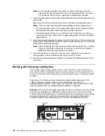
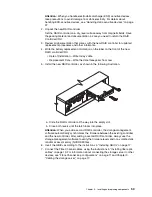
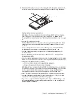
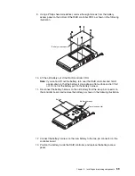
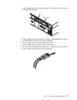
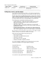
9. Disconnect the battery harness on the battery from the two-pin connector on the
controller board, and remove the battery, as shown in the following illustration.
Set the battery on a dry, level surface.
Attention:
When you handle electrostatic discharge (ESD) sensitive devices,
take precautions to avoid damage from static electricity. For details about
handling ESD-sensitive devices, see “Handling static-sensitive devices” on page
37.
10. Unpack the new RAID controller.
Set the RAID controller on a dry, level surface away from magnetic fields. Save
the packing material and documentation in case you need to return the RAID
controller.
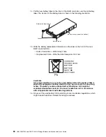
11. Using a Phillips head screwdriver, remove the eight screws from the battery
access panel on the bottom of the replacement RAID controller CRU.
12. Connect the battery harness on the battery to the two-pin connector on the
controller board.
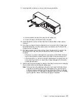
13. Position the battery inside the replacement RAID controller, and replace the
battery-access panel.
14. Copy the battery replacement information from the label on the front of the failed
RAID controller to the label on the front of the replacement RAID controller CRU.
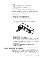
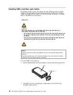
15. Install the new RAID controller, as follows:
a. Slide the RAID controller all the way into the empty slot.
b. Close both levers until the latch locks into place.
Attention:
When you replace the failed RAID controller, the storage-management
software automatically synchronizes the firmware between the existing controller
and the new controller. After replacing a controller, always use the storage-
management software to verify the firmware levels and NVSRAM files.
16. Insert the GBICs according to the instructions in “Installing GBICs” on page 17.
17. Connect the Fibre Channel cables to their original locations, according to the
instructions in “Installing fiber-optic cables” on page 19.
18. If you have a single-controller configuration, turn on power to the storage server
and attached devices. For the proper power-on sequence, see “Turning on the
storage server” on page 25.
Battery
Battery harness
Two-pin connector
Содержание FAStT200 HA
Страница 1: ...IBM IBM FAStT200 and FAStT200 HA Storage Servers Installation and User s Guide SC21 P877 50...
Страница 2: ......
Страница 3: ...IBM IBM FAStT200 and FAStT200 HA Storage Servers Installation and User s Guide SC21 P877 50...
Страница 10: ...viii IBM FAStT200 and FAStT200 HA Storage Servers Installation and User s Guide...
Страница 14: ...xii IBM FAStT200 Storage Server and IBM FAStT200 HA Storage Server Installation and User s Guide...
Страница 16: ...xiv IBM FAStT200 Storage Server and IBM FAStT200 HA Storage Server Installation and User s Guide...
Страница 26: ...8 IBM FAStT200 and FAStT200 HA Storage Servers Installation and User s Guide...
Страница 34: ...16 IBM FAStT200 and FAStT200 HA Storage Servers Installation and User s Guide...
Страница 42: ...24 IBM FAStT200 and FAStT200 HA Storage Servers Installation and User s Guide...
Страница 54: ...36 IBM FAStT200 and FAStT200 HA Storage Servers Installation and User s Guide...
Страница 88: ...70 IBM FAStT200 and FAStT200 HA Storage Servers Installation and User s Guide...
Страница 94: ...76 IBM FAStT200 and FAStT200 HA Storage Servers Installation and User s Guide...
Страница 112: ...94 IBM FAStT200 and FAStT200 HA Storage Servers Installation and User s Guide...
Страница 113: ......

