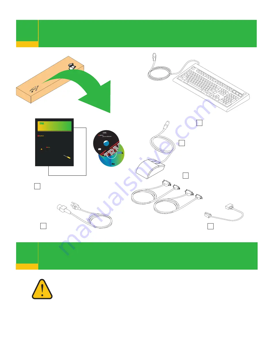
background image

Check inventory

1

The exclamation mark surrounded by a yellow triangle 
denotes caution. A 

CAUTION

 notice indicates the presence 

of a hazard that has the potential of causing moderate or 
minor personal injury. Before doing a step that contains a 
caution icon, read and understand the caution statement that 
accompanies it.

2

Read safety notices

2

2

AIX 5L for 
POWER V 5.2
Documentation CD
(ca_ES)
5765-E62

Licensed Materials-Property of IBM. 
Copyright IBM 1997, 2002
All Rights Reserved.
Recorded in the 
United States of America

Note:

  U.S.Government users,

RESTRICTED RIGHTS-Use,
Duplication, or Disclosure
restricted by GSA ADP Schedule
Contract with IBM Corp.

See the AIX 5.2
Installation Guide 
for Instructions on
the use of this CD.

COMPACT

COMPACT

DIGITAL DATA

DIGITAL DATA

LCD4-1148-00

TM

TM

P/N 80P3920
LCD4-1137-03

Written in U.S.A.

Contains Licensed Material 
Property of IBM. 
Copyright IBM and others 2001, 2004
All Rights Reserved.

Note:

  U.S.Government users,

RESTRICTED RIGHTS-Use,
Duplication, or Disclosure
restricted by GSA ADP Schedule
Contract with IBM Corp.

Version 5.2.0.30

Standalone Diagnostics

Quick Setup Instructions

Completing Your 

System Installation

If you encounter difficulties while setting 
up your system unit, contact your service 
representative for assistance.

The                    pSeries Model 6C4 and Model 6E4 Installation Guide 
was shipped with your system. It is located with the other 
documentation in box 2. Before you begin read all safety notices and 
instructions found in this manual. 

If you have not completed the procedure in the Read Me First brochure, 
locate the Read Me First brochure and complete all of the steps and 
return to this brochure. The Read Me First brochure is located in 
box 1 of your system over pack. 

Items that you provide:

One flat-blade screwdriver

pSeries 630-6C4

Completing Your 

System Installation

“About Your Machine” document,
books, CD-ROMs and other media

Power cables 
(1 standard, 2 optional)

9-pin to 25-pin serial
converter cables (2) 
(optional)

RJ-48 to 9-pin 
converter cable

Keyboard (optional)

If ordered, the keyboard might 
not have shipped in this box.

Note:

 Review your inventory

closely. If any of the components 
shown on this page are missing, or
you encounter any difficulties while 
setting up your system, contact your 
service representative for assistance.

Mouse (optional)

If ordered, the mouse might 
not have shipped in this box.

Содержание @Server pSeries 630 6C4

Страница 1: ...tion set The Read Me First Quick Setup Instructions booklet is located in Box 1 inside the large shipping box that contains the system drawer You must provide the following items One flat blade screwdriver pSeries 630 6C4 Completing Your System Installation Read and understand the caution notices found in this booklet For a complete listing of all safety notices and other documentation related to ...

Страница 2: ...dalone Diagnostics Quick Setup Instructions Completing Your System Installation If you encounter difficulties while setting up your system unit contact your service representative for assistance The pSeries Model 6C4 and Model 6E4 Installation Guide was shipped with your system It is located with the other documentation in box 2 Before you begin read all safety notices and instructions found in th...

Страница 3: ...fer to Hardware Management Console Installation and Operations Guide or visit the After you complete the HMC installation procedure return here and complete this step IBM pSeries and AIX Information Center at http publib16 boulder ibm com pseries index htm Click hardware documentation To connect your HMC to your system connect the HMC serial cable to the HMC1 connector If this is the second HMC be...

Страница 4: ...hics display cable to the back of the display and to the graphics adapter connector To locate installed adapters consult the About Your Machine document Connect the keyboard and mouse when using a graphic display 7 Rear View Connect the keyboard and mouse to the connectors on the rear of the system as shown If a wrist palm rest was included with your keyboard and you want to attach it refer to the...

Страница 5: ...rt S3 Do not run a UPS connected to serial port S2 If you decide to disconnect HACMP you must reset the service processor using the service processor pinhole reset switch before running another application The service processor pinhole reset switch is located on the operator panel Step 16 shows the location of the service processor reset switch Cabling to the serial ports This system is equipped w...

Страница 6: ...vice connected connect the SCSI device terminator If this is not the last device connected go to the step 11 Note The built in SCSI interface is Ultra3 SCSI When a cable is not attached to the SCSI connector on the system the SCSI bus is automatically terminated To set the SCSI device address refer to the SCSI device documentation 10 1 10 2 10 3 10 4 If you are not going to install any additional ...

Страница 7: ...CSI cable to the new SCSI device Repeat substeps 11 1 11 2 and 11 3 for each additional SCSI device that you attach Connect the SCSI device terminator to the last SCSI device To set the SCSI device address see the SCSI device documentation If you are not going to install any additional external SCSI devices go to step 12 1 System Unit to First SCSI Device Cable 2 First External SCSI Device 3 SCSI ...

Страница 8: ...f the cable to the rear RJ 48 connector located on the back of the Model 6C4 Are you using an Ethernet connection 13 If you are unsure whether you are using an Ethernet connection ask your system administrator If you are not using Ethernet or you have already connected your Ethernet to an adapter go to step 14 To connect the Ethernet cable connect the twisted pair cable to one of two RJ 45 connect...

Страница 9: ...s equipped with a three wire power cable and plug for the user s safety Use this power cable with a properly grounded electrical outlet to avoid electrical shock Connect the power cable 14 14 1 14 2 15 1 15 2 15 3 Attach cables to the cable management arm 15 Put the system into the service position The rails lock in the fully extended position with a click Loosely wrap the hook and loop fastener s...

Страница 10: ...ot stop in standby mode check all cables for good connection If you cannot find a problem call your support center for assistance 1 Power On Button 2 Power LED 3 Attention LED 4 SCSI Port Activity 5 Ethernet Port Activity 6 Operator Panel Display 7 FS1 Front Serial Connector RJ 48 8 Service Processor Reset Switch Pinhole 9 System Reset Button Illustration Key If an operating system has been preins...

Страница 11: ...odel D20 I O Drawer located in the eServer pSeries 630 Model 6C4 and Model 6E4 Installation Guide order number SA38 0605 18 1 18 2 After the required cables are installed and the power cables are connected the HMC user interface provides a power on function to turn on the power to the system The power on button on the operator panel can be pushed to initialize the system but the preferred method i...

Страница 12: ...rmation Center http publib16 boulder ibm com pseries index htm Click hardware documentation To access the Verifying the Hardware Operations chapter in the user s guide do the following Select Hardware documentation Select pSeries 630 Model 6C4 and 6E4 Select User s Guide Select the Verifying the Hardware Operations chapter then follow the instructions for the system configuration that most closely...

Отзывы: