background image

If you have internal options, such as adapters, disk drives, 
or memory upgrades that are not installed, install them now.  

Are all of the internal options installed?

3

Check your display or console

4

If you are using an ASCII terminal with a keyboard as the console for
this system, go to “Step 8 Connect the Serial and Parallel Cables”.

If you are using a graphics display with a keyboard and mouse, 
go to “Step 6 Connect the Keyboard and Mouse”.

If you are connecting to a Hardware Management Console (HMC), 
go to “Step 5 Connecting to a Hardware Management Console”. 

Are you connecting to a Hardware 
Management Console (HMC)?

5

If your HMC is already installed, complete this step. If your HMC has not been previously installed, refer to 

Hardware


Management Console Installation


and Operations Guide 

or visit the 

After you complete the HMC installation procedure, return here and complete this step.

IBM               pSeries and AIX 

Information Center at http://publib16.boulder.ibm.com/pseries/index.htm. Click 

hardware documentation

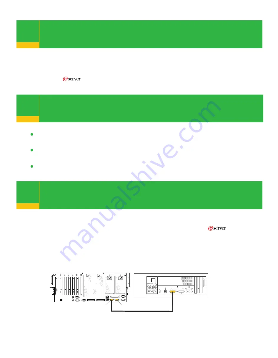
To connect your HMC to your system, connect the HMC serial cable to the HMC1 connector. 
If this is the second HMC being connected to your system, connect the HMC serial connector 
to the HMC2 connector. After connecting the HMC, go to “Step 18 Connect the Serial and 
Parallel Devices.” 

Your system drawer is equipped with two HMC connectors located on the back of the system. 
The connectors are labeled HMC1 and HMC2.

HMC1

HMC2

Model 6C4

HMC

If you need additional information about installing internal options,
visit the IBM               pSeries and AIX Information Center at
http://publib16.boulder.ibm.com/pseries/index.htm. Click  

hardw are  document at ion

.

Содержание @Server pSeries 630 6C4

Страница 1: ...tion set The Read Me First Quick Setup Instructions booklet is located in Box 1 inside the large shipping box that contains the system drawer You must provide the following items One flat blade screwdriver pSeries 630 6C4 Completing Your System Installation Read and understand the caution notices found in this booklet For a complete listing of all safety notices and other documentation related to ...

Страница 2: ...dalone Diagnostics Quick Setup Instructions Completing Your System Installation If you encounter difficulties while setting up your system unit contact your service representative for assistance The pSeries Model 6C4 and Model 6E4 Installation Guide was shipped with your system It is located with the other documentation in box 2 Before you begin read all safety notices and instructions found in th...

Страница 3: ...fer to Hardware Management Console Installation and Operations Guide or visit the After you complete the HMC installation procedure return here and complete this step IBM pSeries and AIX Information Center at http publib16 boulder ibm com pseries index htm Click hardware documentation To connect your HMC to your system connect the HMC serial cable to the HMC1 connector If this is the second HMC be...

Страница 4: ...hics display cable to the back of the display and to the graphics adapter connector To locate installed adapters consult the About Your Machine document Connect the keyboard and mouse when using a graphic display 7 Rear View Connect the keyboard and mouse to the connectors on the rear of the system as shown If a wrist palm rest was included with your keyboard and you want to attach it refer to the...

Страница 5: ...rt S3 Do not run a UPS connected to serial port S2 If you decide to disconnect HACMP you must reset the service processor using the service processor pinhole reset switch before running another application The service processor pinhole reset switch is located on the operator panel Step 16 shows the location of the service processor reset switch Cabling to the serial ports This system is equipped w...

Страница 6: ...vice connected connect the SCSI device terminator If this is not the last device connected go to the step 11 Note The built in SCSI interface is Ultra3 SCSI When a cable is not attached to the SCSI connector on the system the SCSI bus is automatically terminated To set the SCSI device address refer to the SCSI device documentation 10 1 10 2 10 3 10 4 If you are not going to install any additional ...

Страница 7: ...CSI cable to the new SCSI device Repeat substeps 11 1 11 2 and 11 3 for each additional SCSI device that you attach Connect the SCSI device terminator to the last SCSI device To set the SCSI device address see the SCSI device documentation If you are not going to install any additional external SCSI devices go to step 12 1 System Unit to First SCSI Device Cable 2 First External SCSI Device 3 SCSI ...

Страница 8: ...f the cable to the rear RJ 48 connector located on the back of the Model 6C4 Are you using an Ethernet connection 13 If you are unsure whether you are using an Ethernet connection ask your system administrator If you are not using Ethernet or you have already connected your Ethernet to an adapter go to step 14 To connect the Ethernet cable connect the twisted pair cable to one of two RJ 45 connect...

Страница 9: ...s equipped with a three wire power cable and plug for the user s safety Use this power cable with a properly grounded electrical outlet to avoid electrical shock Connect the power cable 14 14 1 14 2 15 1 15 2 15 3 Attach cables to the cable management arm 15 Put the system into the service position The rails lock in the fully extended position with a click Loosely wrap the hook and loop fastener s...

Страница 10: ...ot stop in standby mode check all cables for good connection If you cannot find a problem call your support center for assistance 1 Power On Button 2 Power LED 3 Attention LED 4 SCSI Port Activity 5 Ethernet Port Activity 6 Operator Panel Display 7 FS1 Front Serial Connector RJ 48 8 Service Processor Reset Switch Pinhole 9 System Reset Button Illustration Key If an operating system has been preins...

Страница 11: ...odel D20 I O Drawer located in the eServer pSeries 630 Model 6C4 and Model 6E4 Installation Guide order number SA38 0605 18 1 18 2 After the required cables are installed and the power cables are connected the HMC user interface provides a power on function to turn on the power to the system The power on button on the operator panel can be pushed to initialize the system but the preferred method i...

Страница 12: ...rmation Center http publib16 boulder ibm com pseries index htm Click hardware documentation To access the Verifying the Hardware Operations chapter in the user s guide do the following Select Hardware documentation Select pSeries 630 Model 6C4 and 6E4 Select User s Guide Select the Verifying the Hardware Operations chapter then follow the instructions for the system configuration that most closely...

Отзывы: