background image

172


IBM


xSeries


225


Types


8649:


Hardware


Maintenance


Manual


and


Troubleshooting


Guide

Содержание 8649 - Eserver xSeries 225

Страница 1: ...IBM xSeries 225 Types 8649 Hardware Maintenance Manual and Troubleshooting Guide ...

Страница 2: ......

Страница 3: ...IBM xSeries 225 Types 8649 Hardware Maintenance Manual and Troubleshooting Guide ...

Страница 4: ...ecent version of this document is available at http www ibm com support on the World Wide Web Ninth Edition February 2007 Copyright International Business Machines Corporation 2004 All rights reserved US Government Users Restricted Rights Use duplication or disclosure restricted by GSA ADP Schedule Contract with IBM Corp ...

Страница 5: ... Sie alle Sicherheitshinweise bevor Sie eine Anweisung ausführen Accertarsi di leggere tutti gli avvisi di attenzione e di pericolo prima di effettuare qualsiasi operazione Lea atentamente todas las declaraciones de precaución y peligro ante de llevar a cabo cualquier operación WARNING Handling the cord on this product or cords associated with accessories sold with this product will expose you to ...

Страница 6: ...iv IBM xSeries 225 Types 8649 Hardware Maintenance Manual and Troubleshooting Guide ...

Страница 7: ...ogic Configuration Utility program 15 Using ServeRAID Manager 16 Configuring the Gigabit Ethernet controller 16 Chapter 3 Diagnostics 19 General checkout 19 Checkout procedure 20 Diagnostic tools overview 20 POST error codes and messages 21 Error logs 21 Viewing error logs from the Configuration Setup Utility program 21 Viewing error logs from diagnostic programs 22 ServerGuide error symptoms 22 S...

Страница 8: ...62 Replacing the battery 64 Completing the option installation 66 Replacing the bezel 66 Replacing the side cover 67 Updating your server configuration 67 Connecting external options 68 Installing the server in a rack 68 Input output ports 69 Audio connectors 69 Auxiliary device pointing device connector 70 Ethernet RJ 45 connector 70 Keyboard connector 70 Parallel connector 70 Serial connectors 7...

Страница 9: ...oblems 118 Problem determination tips 119 Chapter 7 Parts listing Type 8649 121 System replaceable units 122 Keyboards CRUs 124 Power cords CRUs 125 Appendix A Getting help and technical assistance 127 Before you call 127 Using the documentation 127 Getting help and information from the World Wide Web 127 Software service and support 128 Hardware service and support 128 Appendix B Related service ...

Страница 10: ...6 United Kingdom telecommunications safety requirement 176 European Union EMC Directive conformance statement 177 Taiwanese Class A warning statement 177 Chinese Class A warning statement 177 Japanese Voluntary Control Council for Interference VCCI statement 177 Index 179 viii IBM xSeries 225 Types 8649 Hardware Maintenance Manual and Troubleshooting Guide ...

Страница 11: ...t differ slightly from your hardware Related publications This Hardware Maintenance Manual and Troubleshooting Guide contains information to help you solve the problem yourself or to provide helpful information to a service technician In addition to this Hardware Maintenance Manual and Troubleshooting Guide the following documentation is provided with your server v Installation Guide This printed ...

Страница 12: ...es Documentation CD Each statement is numbered for reference to the corresponding statement in the Safety Information book The following notices and statements are used in the documentation v Notes These notices provide important tips guidance or advice v Important These notices provide information or advice that might help you avoid inconvenient or problem situations v Attention These notices ind...

Страница 13: ...0 SCSI ports one internal one optional external v Four Universal Serial Bus USB v2 0 ports two on front and two on rear of enclosure v Keyboard port v Mouse port v Audio ports rear Line out Mic Line in v ATA 100 dual channel IDE controller v ATI Rage XL video mini PCI Compatible with SVGA and VGA 8 MB video memory Error LEDs v Fans v Memory v Microprocessors Power supplies v Hot swap some models S...

Страница 14: ... a hard disk drive is in use Power on LED When this LED is lit it indicates that the server is turned on Power control button Press this button to turn the server on and off manually You can install a circular disk called the power control button shield over the power control button to prevent accidental manual power off This disk is provided with your server System error LED When this LED is lit ...

Страница 15: ...s LED This LED is on the Ethernet connector on the back of the server When this LED is lit it indicates that there is an active connection on the Ethernet port Chapter 1 Introducing the IBM xSeries 225 Type 8649 server 5 ...

Страница 16: ...6 IBM xSeries 225 Types 8649 Hardware Maintenance Manual and Troubleshooting Guide ...

Страница 17: ...ation about using this utility program see Using the LSI Logic Configuration Utility program on page 15 v ServeRAID Manager ServeRAID Manager is available as a stand alone program and as an IBM Director extension If a ServeRAID adapter is installed in your server or if you are using the RAID capabilities of the SCSI controller use ServeRAID Manager to define and configure your disk array subsystem...

Страница 18: ...options in the Configuration Setup Utility program some of those changes are reflected in the system information you cannot change settings directly in the system information This choice is on the full Configuration Setup Utility menu only Product Data Select this choice to view the machine type and model of your server the serial number and the revision level or issue date of the BIOS and diagnos...

Страница 19: ...d that it finds If your server has Wake on LAN hardware and software and the operating system supports Wake on LAN functions you can specify a startup sequence for the Wake on LAN functions You can also specify whether the integrated SCSI controller or a PCI SCSI adapter has boot precedence If you enable the boot fail count the BIOS default settings will be restored after three consecutive failure...

Страница 20: ...password is intended to be used by a system administrator it limits access to the full Configuration Setup Utility menu If you set only an administrator password you do not have to type a password to complete the system startup but you must type the administrator password to access the Configuration Setup Utility menu If you set a power on password for a user and an administrator password for a sy...

Страница 21: ...If a later version of the ServerGuide program is available you can download a free image of the ServerGuide Setup and Installation CD or you can purchase the CD To download the image go to the IBM ServerGuide Web page at http www ibm com pc qtechinfo MIGR 4ZKPPT html To purchase the latest ServerGuide Setup and Installation CD go to the ServerGuide fulfillment Web site at http www ibm com pc coupo...

Страница 22: ...r model The ServerGuide program checks your system BIOS service processors and other system hardware to determine if system updates are available The setup program provides a list of tasks that are required to set up your server model On SCSI RAID servers you can run the SCSI RAID configuration program to create logical drives Note Features and functions can vary slightly with different versions o...

Страница 23: ... on a separate diagnostics CD System Partition The ServerGuide program creates a 50 MB System Partition on the default drive The System Partition contains server specific utility programs such as service processor disk operating system DOS utilities system diagnostics flash BIOS updates and other programs Programs in the System Partition vary by server model and not all server models run utility p...

Страница 24: ...can create a setup replication diskette which contains your hardware configuration selections Use this diskette to replicate selections to other servers that are of the same model You can create a operating system replication diskette which contains information that you need to complete multiple installations Not all operating systems support operating system replication diskettes Installing your ...

Страница 25: ...CSI controller with RAID capabilities to configure a RAID level 1 mirrored array after you install the operating system you will lose access to any data or applications that were previously stored on the secondary physical drive of the mirrored pair v To update the firmware and BIOS for an optional ServeRAID controller you must use the IBM ServeRAID Support CD that comes with ServeRAID option v If...

Страница 26: ...he hard disk drives Use the configuration program on the IBM ServeRAID Support CD to configure the integrated SCSI controller with RAID capabilities or to configure an optional IBM ServeRAID controller Notes 1 You cannot use the ServerGuide Setup and Installation CD to configure the optional controllers 2 To update the firmware and BIOS code for an optional ServeRAID controller you must use the IB...

Страница 27: ...CD For the latest device drivers and information about configuring your Ethernet controller go to the IBM Support Web site at http www ibm com support Chapter 2 Configuring your server 17 ...

Страница 28: ...18 IBM xSeries 225 Types 8649 Hardware Maintenance Manual and Troubleshooting Guide ...

Страница 29: ... verify that the failing server is not part of a shared hard disk drive cluster A server might be part of a cluster if v The server is identified as part of a cluster v One or more external storage units are attached to the server and at least one of the attached storage units is also attached to another server or unidentifiable source v One or more servers are located near the failing server If t...

Страница 30: ...U index on page 101 YES Run the diagnostic programs If necessary see Diagnostic programs error codes and messages on page 22 If you receive an error see Chapter 6 Symptom to FRU index on page 101 If the diagnostic programs were completed successfully and you still suspect a problem see Undetermined problems on page 118 Diagnostic tools overview The following tools are available to help you identif...

Страница 31: ...forms a series of tests to check the operation of server components and some of the options installed in the server This series of tests is called the power on self test or POST If POST finishes without detecting any problems a single beep sounds and the first screen of your operating system or application program appears If POST detects a problem more than one beep sounds and or an error message ...

Страница 32: ...e installed v Ensure that there are no duplicate SCSI IDs or IRQ assignments v Ensure that the hard disk drive is connected properly The Operating System Installation program continuously loops Make more space available on the hard disk The ServerGuide program will not start your NOS CD Ensure that the NOS CD you have is supported by the ServerGuide program See the ServerGuide Setup and Installati...

Страница 33: ...tic programs are run The error code format is as follows fff ttt iii date cc text message where fff is the three digit function code that indicates the function being tested when the error occurred For example function code 089 is for the microprocessor ttt is the three digit failure code that indicates the exact test failure that was encountered These codes are for trained service personnel see D...

Страница 34: ... result occurs when a possible problem is reported during the diagnostic test such as when a device driver is not found test specific string is additional information that you can use to analyze the problem Starting the diagnostic programs Complete the following steps to start the diagnostic programs 1 Turn on the server and watch the screen Note To run the diagnostic programs you must start the s...

Страница 35: ... such as system configuration memory contents interrupt request IRQ use direct memory access DMA use device drivers and so on by selecting Hardware Info from the top of the screen If the diagnostic programs do not detect any hardware errors but the problem persists during normal server operations a software error might be the cause If you suspect a software problem see the information that comes w...

Страница 36: ...roprocessor 2 error D32 Microprocessor 2 problem also turns on system error LED on the front bezel Microprocessor 2 problem also turns on system error LED on the front bezel Fan error D2 D19 D55 No function Fan failure Hard disk error LEDs on hot swap hard disk drives Hot swap hard disk drive failure Hot swap hard disk drive failure Diagnostic error code tables For descriptions of the error codes ...

Страница 37: ...oot block recovery jumper J12 Keep data Normal Clear data Configure Recovery no jumper J12 6 Remove the boot block recovery jumper from pins 1 and 2 7 Replace any adapters that were removed then replace the frame support bracket and replace the side cover See Removing and installing the support bracket on page 38 and Replacing the side cover on page 67 8 Connect the server to a power source keyboa...

Страница 38: ...at impede access to the jumper The following illustration shows the location of the jumper on the system board 1 2 3 1 2 3 1 2 3 1 2 3 1 2 3 CMOS recovery jumper JBAT1 Boot block recovery jumper J12 Keep data Normal Clear data Configure Recovery no jumper J12 6 Move the CMOS recovery jumper from pins 1 and 2 to pins 2 and 3 7 Wait 60 seconds then return the CMOS recovery jumper to pins 1 and 2 8 R...

Страница 39: ...it is important to know the minimum configuration required for a system to start see page 109 Troubleshooting the Ethernet controller This section provides troubleshooting information for problems that might occur with the 10 100 1000 Mbps Ethernet controller Network connection problems If the Ethernet controller cannot connect to the network check the following conditions v Make sure that the cab...

Страница 40: ... Try changing the IRQ assigned to the Ethernet controller or the other device For example for NetWare Versions 3 and 4 it is recommended that disk controllers not share interrupts with LAN controllers v Make sure that you are using the most recent device driver available from the World Wide Web v Reseat or replace the adapter Ethernet link status LED does not work Check the following v Make sure t...

Страница 41: ...ng is allowed for PCI devices some devices do not function well when they share an interrupt with a dissimilar PCI device Try changing the IRQ assigned to the Ethernet adapter or the other device v Reseat or replace the adapter The Ethernet controller stopped working without apparent cause Check the following v Try a different connector on the hub v Reinstall the device drivers See your operating ...

Страница 42: ...32 IBM xSeries 225 Types 8649 Hardware Maintenance Manual and Troubleshooting Guide ...

Страница 43: ... serverproven compat us on the World Wide Web System reliability considerations To help ensure proper system cooling and system reliability make sure that v Each of the drive bays has a drive or a filler panel and electromagnetic compatibility EMC shield installed v If the server has redundant power each of the power supply bays has a power supply installed in it v There is adequate space around t...

Страница 44: ...wer source but is not turned on the operating system does not run and all core logic is shut down however the server can respond to remote requests to turn on the server The power on LED flashes to indicate that the server is connected to an ac power source but is not turned on standby mode Turning on the server Notes 1 Turn on all external devices such as the monitor before turning on the server ...

Страница 45: ... have more than one power cord To remove all electrical current from the device ensure that all power cords are disconnected from the power source 1 2 Note After turning off the server wait at least 5 seconds before you press the power control button to turn on the server again The server can be turned off in any of the following ways v You can turn off the server from the operating system if your...

Страница 46: ...disconnect all external cables 5 Unlock the side cover then pull the cover release latch away from the server and push the cover toward the rear of the server Lift the side cover off the server and set it aside Key lock Cover release latch Attention For proper cooling and airflow replace the cover before turning on the server Operating the server with the cover removed might damage server componen...

Страница 47: ...it from the bezel see the illustration on page 47 If the hot swap lock bar will not rotate press the top of the hot swap lock bar to release the lock mechanism 3 Locate the bezel release lever then press the bezel release lever toward the front of the server 4 Pull the top of the bezel away from the chassis then push the bezel down to disengage the bottom tabs 5 Remove the bezel from the server an...

Страница 48: ...on page 129 and Installation guidelines on page 33 2 Remove the side cover Removing the side cover on page 36 3 If your server comes with a standard support bracket similar to the support bracket in the following illustration complete the following steps a Pull out on the rear end of the support bracket at a 45 angle b Disengage the front end of the support bracket from the server and set the brac...

Страница 49: ...s Before you install an adapter review the following information v Read the documentation that comes with your operating system v Locate the documentation that comes with the adapter and follow those instructions in addition to the instructions in this chapter If you need to change the switch or jumper settings on your adapter follow the instructions that come with the adapter v Installation of an...

Страница 50: ...gh 5 v The server scans the AGP slot mini PCI slot 6 PCI expansion slot 1 and PCI X expansion slots 2 through 5 to assign system resources Then the server starts the PCI devices in the following order if you have not changed the default startup sequence AGP slot mini PCI slot 6 PCI expansion slot 1 system board integrated drive electronics IDE or SCSI devices including optional ServeRAID 6i contro...

Страница 51: ...future use Attention Expansion slot covers must be installed on all vacant slots This maintains the electronic emissions standards of the server and ensures proper ventilation of server components 8 Set any jumpers or switches on the adapter or system board according to the documentation that comes with the adapter Attention Avoid touching the components and gold edge connectors on the adapter 9 I...

Страница 52: ...l length adapter rotate the front adapter support bracket to the closed locked position 14 Reinstall the rear adapter retention bracket then rotate the bracket to the closed locked position Note If any adapters in your server are large or have heavy cables attached to them you can remove the rear adapter retention bracket and secure all of the adapters with expansion slot screws The expansion slot...

Страница 53: ...SI adapter or cable option is required to connect external SCSI devices Complete the following steps to cable an optional SCSI adapter 1 Install the SCSI adapter see Installing an adapter on page 40 2 Connect the SCSI signal cable to the adapter and to one or more of the signal cable connectors to the rear of the SCSI devices 3 Connect the SCSI activity indicator cable to the adapter and to the SC...

Страница 54: ...at supports hot swap drives which you can replace without turning off the server Internal drive bays All server models come with an IDE CD ROM drive in bay 1 and a 3 5 in 1 44 MB diskette drive in bay 3 Depending on your server model it will also come with either six hot swap hard disk drive bays or a hard disk drive in bay 7 Server with hot swap hard disk drives Bay 1 Bay 2 Bay 3 Bay 4 Bay 5 Bay ...

Страница 55: ...e bay numbers are 4 through 9 from top to bottom with SCSI IDs of 0 through 5 from bottom to top The hot swap bays are below the removable media drive bays Diskette drives tape drives CD ROM DVD CD RW and DVD ROM drives are examples of removable media drives You can install removable media drives in bays 1 2 and 3 only You can install a 3 5 in slim high or 5 25 in half high removable media drive s...

Страница 56: ... xSeries Documentation CD If the amber hard disk drive status LED for a drive is lit continuously that drive is faulty and requires replacement When the hard disk drive status LED indicates a drive fault you can replace the drive without turning off the server For increased security the hot swap drives and filler panels are locked in the server by the hot swap lock bar The hot swap lock bar cannot...

Страница 57: ... Open the server door 3 Remove the hot swap lock bar a Unlock the side cover lock b Rotate the hot swap lock bar forward and remove it from the bezel If the hot swap lock bar will not rotate press the top of the hot swap lock bar to release the lock mechanism 4 Remove the filler panel from one of the empty hot swap bays by inserting your finger into the depression at the left side of the filler pa...

Страница 58: ...p hard disk drive is printed on the hot swap lock bar Table 5 lists the SCSI IDs for the hard disk drives and backplane that are connected to one channel in hot swap hard disk drive models In the typical configuration the standard hard disk drives and backplane are connected to channel A Table 5 SCSI IDs for standard hot swap hard disk drives and backplane Device SCSI ID Drive bay 9 0 Drive bay 8 ...

Страница 59: ...age Clear any cables that might impede the replacement of the drive cage 9 Connect one end of the SCSI signal cable into the back of the drive and make sure that the other end of this cable is connected into the SCSI connector on the system board See Power and signal cables for internal drives on page 54 for additional information about cabling drives and System board internal connectors on page 9...

Страница 60: ...Removing and installing the support bracket on page 38 15 Replace the side cover see Replacing the bezel on page 66 16 Reconnect the external cables and power cords then turn on the attached devices and the server 50 IBM xSeries 225 Types 8649 Hardware Maintenance Manual and Troubleshooting Guide ...

Страница 61: ...les and other equipment specified in the documentation that comes with the drive Complete the following steps to install a removable media drive in bay 2 see Internal drive bays on page 44 1 Review the safety information beginning on page 129 and Installation guidelines on page 33 2 Turn off the server and all attached devices 3 Disconnect all power cords then disconnect all external cables 4 Remo...

Страница 62: ...ustments or performance of procedures other than those specified herein might result in hazardous radiation exposure DANGER Some laser products contain an embedded Class 3A or Class 3B laser diode Note the following Laser radiation when open Do not stare into the beam do not view directly with optical instruments and avoid direct exposure to the beam Class 1 Laser Product Laser Klasse 1 Laser Klas...

Страница 63: ...en connect one end of the appropriate signal cable into the back of the drive and make sure that the other end of this cable is connected into the appropriate IDE or SCSI connector on the system board v If you are installing a SCSI removable media drive use the one drop SCSI cable that comes with the drive and connect it to SCSI channel B SCSI2 See Power and signal cables for internal drives on pa...

Страница 64: ...two IDE devices are used on a single cable one must be designated as the master device and the other as the subordinate device otherwise the server might not recognize some of the IDE devices The master and subordinate designation is determined by switch or jumper settings on each IDE device The following cables are provided v Power cables Four wire power cables connect the drives to the power sup...

Страница 65: ... not have to be the same size speed type and technology as the DIMMs you installed in DIMM 3 and DIMM 4 memory connectors However the size speed type and technology of the DIMMs you install in DIMM 1 and DIMM 2 memory connectors must match each other 6 Install only 133 MHz memory bus 2 5 V 184 pin double data rate DDR PC2100 registered synchronous dynamic random access memory SDRAM with error corr...

Страница 66: ...own into the connector by applying pressure on both ends of the DIMM simultaneously The retaining clips snap into the locked position when the DIMM is firmly seated in the connector If there is a gap between the DIMM and the retaining clips the DIMM has not been correctly installed Open the retaining clips remove the DIMM and then reinsert it DIMM 1 DIMM 3 DIMM 2 DIMM 4 9 If you have other options...

Страница 67: ...d in socket CPU1 of the system board Notes 1 To order additional microprocessor options contact your IBM marketing representative or authorized reseller 2 Terminator cards are not required for empty microprocessor sockets However for airflow an empty microprocessor socket must contain a microprocessor baffle 3 The microprocessor speeds are automatically set for this server therefore you do not nee...

Страница 68: ...stalling the additional microprocessor The following illustration shows how to install an additional microprocessor DIMMs Microprocessor release lever Captive screws Heatsink 2 Microprocessor 2 Microprocessor baffle Complete the following steps to install an additional microprocessor 1 Review the safety information beginning on page 129 Installation guidelines on page 33 and Handling static sensit...

Страница 69: ...oprocessor into the socket 2 Make sure that the microprocessor is oriented and aligned correctly with pin number 1 in the socket before you try to close the microprocessor release lever The following illustration shows the alignment marks for both microprocessors and sockets Microprocessor 2 Microprocessor 1 Microprocessor socket 2 Microprocessor socket 1 Alignment marks Alignment marks c Center t...

Страница 70: ...nk while tightening them 13 Install the air baffle 14 Install the adapter airflow guide a Rotate the front and rear adapter retention brackets to the open unlocked position b Slide the adapter airflow guide into the guides on the air baffle and front adapter support bracket then push it into place using care to not damage any cables c Rotate the front and rear adapter retention brackets to the clo...

Страница 71: ...en attach and tighten the nuts 4 Thread a cable through the rope clip and around an object that is not part of or permanently secured to the building structure or foundation and from which the cable cannot be removed Fasten the cable ends together with a lock After you add the security cable be certain it does not interfere with other cables connected to the server Rope clip 5 If you have other op...

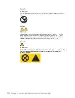
Страница 72: ...atement 8 CAUTION Never remove the cover on a power supply or any part that has the following label attached Hazardous voltage current and energy levels are present inside any component that has this label attached There are no serviceable parts inside these components If you suspect a problem with one of these parts contact a service technician Statement 12 CAUTION The following label indicates a...

Страница 73: ...ower supply out of the bay and set it aside 3 Make sure the power supply handle is in the open position then slide the power supply all the way into the chassis before placing the power supply handle into the locked position 4 If the server is not on turn on the server 5 Verify that the dc power LED and the ac power LED on the power supply are lit indicating that the power supply is operating prop...

Страница 74: ...er 33F8354 or an equivalent type battery recommended by the manufacturer If your system has a module containing a lithium battery replace it only with the same module type made by the same manufacturer The battery contains lithium and can explode if not properly used handled or disposed of Do not v Throw or immerse into water v Heat to more than 100 C 212 F v Repair or disassemble Dispose of the b...

Страница 75: ...Rotate the front and rear adapter retention brackets to the open unlocked position b Slide the adapter airflow guide into the guides on the air baffle and front adapter support bracket then push it into place using care to not damage any cables c Rotate the front and rear adapter retention brackets to the closed locked position 12 Replace the support bracket and side cover See Removing and install...

Страница 76: ... server into electrical outlets you will have to wait approximately 20 seconds before pressing the power control button Replacing the bezel The following illustration shows how to install the bezel on the server Complete the following steps to replace the bezel 1 Insert the two tabs on the bottom of the bezel into the matching holes on the server chassis 2 Push the top of the bezel toward the serv...

Страница 77: ...ition inserting the tabs at the top of the side cover into the matching slots in the server chassis 4 Slide the side cover forward until it locks in place Press down on the cover release latch button as you close the cover release latch to lock the side cover Key lock Cover release latch 5 For hot swap hard disk drive models open the server door and hold the hot swap lock bar in the closed positio...

Страница 78: ... an optional SCSI adapter or use channel B on the integrated SCSI controller for external devices you can attach external SCSI devices such as a SCSI storage expansion enclosure to your server To use channel B for external SCSI devices remove the SCSI knockout from the rear of the server and secure the free end of the channel B cable in the new opening You can attach additional external options to...

Страница 79: ... SCSI knockout USB 2 USB 1 Mic pink Line in blue Line out green Ethernet Video 1 1 2 2 The following sections describe these connectors If you have an optional Remote Supervisor Adapter II system management adapter installed in PCI slot 1 your server also has an additional Ethernet connector an additional serial connector and an Advanced System Management ASM Interconnect connector See the documen...

Страница 80: ...onnector 6 4 2 1 3 5 Ethernet RJ 45 connector The following illustration shows an Ethernet connector 1 8 Link LED green Activity LED green Connect a Category 3 4 or 5 unshielded twisted pair UTP cable to this connector The 100BASE TX and 1000BASE T Fast Ethernet standards require Category 5 or higher cabling For more information about the Ethernet controller see the User s Guide on the IBM xSeries...

Страница 81: ... drive backplane You can attach additional internal SCSI devices to the other internal SCSI channel B connector or you can use channel B for external SCSI devices To use channel B for external SCSI devices remove the SCSI knockout from the rear of the server and secure the free end of an optional channel B cable in the new opening If you want to attach external SCSI devices to the server without u...

Страница 82: ...SI devices you must order an additional SCSI cable remove the SCSI knockout from the rear of the server and connect the new cable from the system board to this opening To select and order the correct cables for use with external devices contact your IBM reseller or IBM marketing representative When using an optional SCSI adapter you must also connect the SCSI adapter to the SCSI LED J18 connector ...

Страница 83: ...nector The super video graphics array SVGA video adapter is installed in mini PCI slot 6 on the system board There is one video connector on the rear of the server Use the video connector to connect a monitor or other display The following illustration shows an industry standard 15 pin analog video connector on the rear of the server 1 5 11 15 Chapter 4 Installing options 73 ...

Страница 84: ...74 IBM xSeries 225 Types 8649 Hardware Maintenance Manual and Troubleshooting Guide ...

Страница 85: ...ations on page 33 To remove the power button complete the following steps 1 Turn off the server if it is on 2 Unplug the server and disconnect the power cord then disconnect all external cables 3 Remove the side cover See Removing the side cover on page 36 4 Remove the front bezel See Removing the bezel on page 37 5 If your server has hot swap hard disk drives installed remove them See Hot swap ha...

Страница 86: ...read the power button and LED panel cables through the aperture in the chassis and bottom release latch 2 Connect the power button and LED panel cables to the power button and LED panel connectors on the system board 3 Press in on the tab on the left side of the panel then squeeze the top and bottom of the right side of the panel and carefully push the panel into place in the aperture in the chass...

Страница 87: ...he two captive screws loosened pivot the leaf spring assemblies outward and out of the notches on the fan sink assembly c Lift the heat sink up and out of the server Note It might be necessary to gently twist the heat sink to loosen it from the microprocessor Important Be careful when handling the adhesive material on the microprocessor If the adhesive material on the microprocessor will be reused...

Страница 88: ...e the heat sink on a clean work surface 2 Remove the cleaning pad from its package and unfold it completely 3 Use the cleaning pad to wipe the thermal grease from the bottom of the heat sink Note Be sure that all of the thermal grease is removed 4 Use a clean area of the cleaning pad to wipe the thermal grease from the microprocessor then dispose of the cleaning pad after all of the thermal grease...

Страница 89: ...e bezel on page 37 4 Remove the side cover See Removing the side cover on page 36 5 Remove the frame support bracket See Removing and installing the support bracket on page 38 6 Remove any hard disk drives or drive fillers from the drives 7 Disconnect the hard disk drive cables that connect to the system board 8 Remove the screw from the front of the hard disk drive cage 9 Move the cage slightly i...

Страница 90: ...4 Remove the side cover See Removing the side cover on page 36 5 Remove the frame support bracket See Removing and installing the support bracket on page 38 6 Remove any hard disk drives or drive fillers from the drives 7 Disconnect the hard disk drive cables that connect to the system board and the backplane 8 Press down on the drive cage release latch and swing the drive cage out 9 Remove the sc...

Страница 91: ...he server and disconnect the power cord then disconnect all external cables 3 Remove the cover See Removing the side cover on page 36 4 Remove the frame support bracket See Removing and installing the support bracket on page 38 5 Disconnect internal cables from the system board and drives 6 Remove the screws from the rear of the server 7 Gently move the power supply away from the chassis and lift ...

Страница 92: ...f the power supply with the tab slots on the underside of the top rear of the chassis and slide the power supply toward the rear of the chassis 2 Secure the power supply to the rear of the chassis with the four screws 82 IBM xSeries 225 Types 8649 Hardware Maintenance Manual and Troubleshooting Guide ...

Страница 93: ...er and disconnect the power cord then disconnect all external cables 3 Remove the side cover See Removing the side cover on page 36 4 Remove the frame support bracket See Removing and installing the support bracket on page 38 5 Remove the fan cable from the system board 6 Remove the adapter support bracket and fan housing 7 Use side cutters to cut the four rubber extensions on the adapter support ...

Страница 94: ...owing steps 1 Place the fan in position on the adapter support bracket 2 Guide the rubber extensions through the apertures 3 Use needle nosed pliers to pull the extensions through the apertures 4 Reconnect cables 5 Replace the frame support bracket 6 Replace the side cover 84 IBM xSeries 225 Types 8649 Hardware Maintenance Manual and Troubleshooting Guide ...

Страница 95: ...port bracket on page 38 5 Remove the airflow guide and air baffle 6 Remove the fan cable from the system board 7 Use side cutters to sever the four rubber extensions on the outside of the server 8 Gently pry the fan away from the server and lift it up and out Rubber extensions To install the new rear fan assembly complete the following steps 1 Place the fan in position at the rear of the server 2 ...

Страница 96: ...support bracket See Removing and installing the support bracket on page 38 5 Remove both adapter retaining brackets and the adapter in PCI adapter slot 1 see Installing an adapter on page 40 6 Disconnect the cables 7 Remove the air flow guide and the air baffle from over the microprocessor 8 Find the video adapter in the mini PCI type III slot on the system board and remove the video cable from th...

Страница 97: ... server and all attached devices 3 Disconnect all power cords then disconnect all external cables 4 Remove the side cover see Removing the side cover on page 36 5 Temporarily remove any adapters installed in PCI slot 1 see Installing an adapter on page 40 Temporarily store these adapters in a static protective location 6 Locate the mini PCI slot on the system board Check the instructions that come...

Страница 98: ...ere is a gap between the adapter and the retaining clips the adapter has not been properly installed In this case open the retaining clips and remove the adapter then reinsert the adapter You might need to disengage the locking clips on the two stand offs to remove the adapter Attention Be certain that the adapter is correctly seated in the expansion slot before you turn on the server Incomplete i...

Страница 99: ... due to the weight of the server To remove the system board complete the following steps 1 Turn off the server if it is on 2 Unplug the server and disconnect the power cord then disconnect all external cables 3 Remove the side cover See Removing the side cover on page 36 4 Remove the front bezel See Removing the bezel on page 37 5 Remove the frame support bracket See Removing and installing the su...

Страница 100: ... and lift the front of the system board to clear the locating pin then slide the board forward to clear the EMC shield 14 Lift the system board out of the server chassis To replace the system board reverse the steps 90 IBM xSeries 225 Types 8649 Hardware Maintenance Manual and Troubleshooting Guide ...

Страница 101: ...CI type III slot 6 PCI6 Remote Supervisor Adapter II JMGT1 System board internal connectors The following illustration shows the internal connectors on the system board Rear fan 1 SYSFAN1 Rear fan 2 SYSFAN2 Main power POWER1 Power POWER2 CD audio JCD1 SCSI LED J18 Diskette drive FDD1 Secondary IDE IDE2 Primary IDE IDE1 Error LED JER2 Cover switch JCI2 Front panel switch LEDs JFP1 SCSI channel A SC...

Страница 102: ... the system board You might need to refer to this illustration when solving problems with the server Rear fan 1 SYSFAN1 Rear fan 2 SYSFAN2 Main power POWER1 Power POWER2 CD audio JCD1 SCSI LED J18 Diskette drive FDD1 Secondary IDE IDE2 Primary IDE IDE1 Error LED JER2 Cover switch JCI2 Front panel switch LEDs JFP1 SCSI channel A SCSI1 SCSI channel B SCSI2 Wake on LAN JWL PCI fan SYSFAN5 Center fan ...

Страница 103: ...lso turns on system error LED on the front bezel Microprocessor 2 error D32 Microprocessor 2 problem also turns on system error LED on the front bezel Microprocessor 2 problem also turns on system error LED on the front bezel Fan error D2 D19 D55 D56 No function Fan failure Hard disk error LEDs on hot swap hard disk drives Hot swap hard disk drive failure Hot swap hard disk drive failure Chapter 5...

Страница 104: ...r cord then disconnect all external cables 3 Remove the side cover See Removing the side cover on page 36 4 Disconnect the CD ROM connector and power cables 5 Remove the two screws from the CD ROM drive cage 6 Gently slide the CD ROM drive toward the front of the server and lift it out For instructions to replace the CD ROM drive see Installing a 5 25 inch removable media drive on page 51 94 IBM x...

Страница 105: ...the server if it is on 2 Unplug the server and disconnect the power cord then disconnect all external cables 3 Remove the side cover See Removing the side cover on page 36 4 Disconnect the cables 5 Remove the two screws from the diskette drive cage 6 Gently slide the diskette drive toward the front of the server and lift it out To replace the diskette drive reverse the steps Chapter 5 Field replac...

Страница 106: ...ables 3 Remove the side cover See Removing the side cover on page 36 4 Remove the front bezel See Removing the bezel on page 37 5 Remove the handle assembly See Handle assembly on page 99 6 Remove the four screws from the back of the server and put them in a safe place 7 Using a screwdriver gently pry the cover away from the server in the rear and slide the unit away from the server To replace the...

Страница 107: ...server and disconnect the power cord then disconnect all external cables 3 Remove the side cover See Removing the side cover on page 36 4 Remove the front bezel See Removing the bezel on page 37 5 Remove the CD ROM drive See CD ROM drive on page 94 6 Pull down from inside the server to release the latch tab 7 From the underside grasp the bezel release latch in the center and gently pull it back an...

Страница 108: ...OM drive See Installing a 5 25 inch removable media drive on page 51 for instructions 3 Replace the front bezel See Replacing the bezel on page 66 4 Replace the side cover See Replacing the side cover on page 67 5 Connect all external cables then connect the power cord and plug in the server 6 Turn on the server 98 IBM xSeries 225 Types 8649 Hardware Maintenance Manual and Troubleshooting Guide ...

Страница 109: ...remove the top handle a Carefully use a flat blade screwdriver to push in the tabs inside the plastic cover on the top of the system then remove the plastic cover Store the cover for possible future use b Grasp the metal handle and slide it toward the rear of the server to remove it from your server Store the metal handle for possible future use To remove the handle support complete the following ...

Страница 110: ...is on 2 Unplug the server and disconnect the power cord then disconnect all external cables 3 Remove the side cover See Removing the side cover on page 36 4 Rotate the rear adapter retainer to the open position 5 Grasp the rear adapter retainer and gently slide the top and bottom tabs out of the notches To replace the rear adapter retainer reverse the steps 100 IBM xSeries 225 Types 8649 Hardware ...

Страница 111: ...ond column then try the server again to see if the problem has been corrected Note Try reseating a suspected component or reconnecting a cable before replacing the component The POST BIOS code displays POST error codes and messages on the screen Beep symptoms Beep symptoms are short tones or a series of short tones separated by pauses intervals without sound See the examples in the following table...

Страница 112: ...4 Secondary interrupt mask register failed System board 2 2 2 Keyboard controller failed 1 Keyboard 2 System board 2 2 3 CMOS power failure and checksum check failed 1 Battery 2 System board 2 4 1 Video failed screen believed operable System board 3 1 1 Timer tick interrupt failed System board 3 1 2 Interval timer channel 2 failed System board 3 1 3 RAM test failed above address OFFFFH 1 DIMM 2 Sy...

Страница 113: ...rs during POST System board No beep no video and the system attention LED is off System board No beep no video and a system board error LED is on v See System board error LEDs on page 26 BIST failed Microprocessor Diagnostic error codes Note In the following error codes if XXX is 000 195 or 197 do not replace a FRU The description for these error codes are 000 The test passed 195 The Esc key was p...

Страница 114: ...System board 030 XXX 000 Failed Internal SCSI interface test System board 035 XXX 099 1 Integrated RAID function on system board is damaged 2 No RAID adapters were found 3 If adapter is installed re check connection 035 XXX S99 Failed RAID test on PCI slot S check System Error Log before replacing a FRU 1 RAID Adapter 2 SCSI Backplane 3 Cable 035 XXX SNN Check System Error Log before replacing a F...

Страница 115: ...ry 165 342 000 Service Processor Failed 1 Ensure latest firmware levels for ASM and BIOS 2 Disconnect all server and option power cords from server wait 30 seconds reconnect and retry 3 System Board 180 XXX 000 Diagnostics LED failure Run Diagnostic LED test for the failing LED 180 XXX 001 Failed Front LED panel test Information LED Panel 180 XXX 002 Failed Diagnostics LED panel test System board ...

Страница 116: ...r to the Help and Service Information appendix of the tape drive s User Guide 4 System Board or SCSI Controller Run SCSI Controller Diagnostic to determine if the SCSI bus is functioning properly 264 XXX 999 Errors on multiple tape drives see error text for more info See error messages text in the PC Doctor error log for detailed information on each individual tape drive error 301 XXX 000 Failed K...

Страница 117: ...ch 1 Reseat connector 2 Switch Card 3 System Board Diskette drive in use light stays on or the system bypasses the diskette drive or the diskette drive does not work 1 If there is a diskette in the drive verify that a The diskette drive is enabled in the Configuration Setup utility program b The diskette is good and not damaged Try another diskette if you have one c The diskette is inserted correc...

Страница 118: ...or System timer test failed System board Memory test failed v DIMM v System board RAM refresh test failed System board ECC controller logic System board CMOS RAM test failed System board Keyboard controller test failed System board External cache test failed Microprocessor PCI test failed System board USB interface test failed System board USB port test failed System board Video test failed Mini P...

Страница 119: ...board Speaker test failed System board Mouse test failed 1 Mouse 2 System board Hot swap power supply LED errors Use the information in this section to solve power supply problems Note The minimum configuration required for the dc good light to be lit is v Power supply v Power cage assembly if installed v System board set switch 7 of SW1 to bypass the power switch see System board internal connect...

Страница 120: ...er supply 4 Power cage assembly if installed 5 System board On On Power is working properly N A POST error codes In the following error codes X can be any number or letter Note See System replaceable units on page 122 to determine which components should be replaced by a field service technician Error code symptom FRU action 062 Three consecutive boot failures using the default configuration 1 Run...

Страница 121: ...tup sequence information corrupted 1 Run the Configuration Setup Utility program 2 System board 187 VPD serial number not set 1 Set serial number in the Configuration Setup Utility program 2 System board 188 EEPROM CRC 2 damaged 1 Run the Configuration Setup Utility program 2 System board 189 An attempt made to enter the system with invalid passwords 1 Run the Configuration Setup Utility program 2...

Страница 122: ... System board 1762 Hard drive configuration error IDE only 1 Hard disk drive 2 Hard disk cables 3 Run the Configuration Setup Utility program 4 System board 178X Hard drive error IDE only 1 Hard disk cables 2 Hard disk adapter 3 Hard disk drive 4 System board 1800 No more hardware interrupt available for PCI adapter 1 Run the Configuration Setup Utility program 2 Remove adapter 1801 No more ROM sp...

Страница 123: ... 3 System board 00180200 No more I O space available for PCI adapter 1 Run the Configuration Setup Utility program 2 Adapter 3 System board 00180300 No more memory above 1MB for PCI adapter 1 Run the Configuration Setup Utility program 2 Adapter 3 System board 00180400 No memory below 1 MB for PCI adapter 1 Run the Configuration Setup Utility program 2 Adapter 3 System board 00180500 PCI option RO...

Страница 124: ... System replaceable units on page 122 to determine which components should be replaced by a field service technician Message Action DASD Over Temperature level critical direct access storage device bay x was over temperature Ensure that the system is being properly cooled see System reliability considerations on page 33 DASD Over recommended Temperature sensor x level warning DASD bay x had over t...

Страница 125: ...failure 1 Check connections to fan x 2 Replace fan x Fan x fault level critical fan x beyond recommended RPM range 1 Check connections to fan x 2 Replace fan x Fan x outside recommended speed action Replace fan x Power error messages Note See System replaceable units on page 122 to determine which components should be replaced by a field service technician Message Action Power supply x current sha...

Страница 126: ...Power checkout on page 29 System shutoff due to x V over voltage level critical system shutoff due to x supply over voltage 1 Check the power supply connectors 2 Power supply 3 Power cage assembly if installed System shutoff due to x V under voltage level critical system shutoff due to x supply under voltage 1 Check the power supply connectors 2 Power supply 3 Power cage assembly if installed Syst...

Страница 127: ...ithin normal operating specifications see Features and specifications on page 3 DASD checkout Note See System replaceable units on page 122 to determine which components should be replaced by a field service technician Message Action Hard drive x removal detected level critical hard drive x has been removed Information only take action as appropriate Host built in self test BIST Note See System re...

Страница 128: ...ices list is incorrect or the system is inoperative Notes 1 Damaged data in CMOS can cause undetermined problems 2 Damaged data in BIOS code can cause undetermined problems Check the LEDs on all the power supplies If the LEDs indicate the power supplies are working correctly complete the following steps 1 Turn off the server 2 Be sure the server is cabled correctly 3 Remove or disconnect the follo...

Страница 129: ...ems Is the failure repeatable Has this configuration ever worked If it has been working what changes were made prior to it failing Is this the original reported failure v Diagnostics version Type and version level v Hardware configuration Print print screen configuration currently in use BIOS level v Operating system software Type and version level Note To eliminate confusion identical systems are...

Страница 130: ...120 IBM xSeries 225 Types 8649 Hardware Maintenance Manual and Troubleshooting Guide ...

Страница 131: ...hapter 7 Parts listing Type 8649 This parts listing supports the xSeries 225 Type 8649 models 42X 4AX 4BX 52X 5AX 5BX 62X 6AX 6BX 1 2 3 4 5 6 7 8 9 10 11 12 13 14 15 16 17 18 Copyright IBM Corp 2004 121 ...

Страница 132: ...0 FRU 14 Microprocessor 533 2 8B 0K L3 models 52X 5AX 5BX 59P4845 FRU 14 Microprocessor 533 3 06 0K L3 models 62X 6AX 6BX 71P8340 FRU 15 System board all models 43W9207 FRU 16 Memory 256 MB PC2100 ECC DIMM all models 73P2872 CRU 17 Retainer I O cards all models 59P4790 FRU 18 Air baffle all models 24P1284 FRU Bezel kit all models v Filler bezel 2 v Blank bezel 2 00N7082 CRU Duct assembly 80 mm fan...

Страница 133: ...le all models 71P8107 FRU Mouse assembly all models 24P0383 CRU Air panel all models 90P0924 FRU Control panel assembly all models 24P2621 FRU PCI video adapter alternate all models 59P2705 FRU Power button kit all models 19K4940 FRU Power cord all models 6952301 CRU Power button shield all models 71P8467 CRU Power supply 425 watt 42X 4AX 52X 5AX 62X 6AX 6CG 49P2042 FRU Power supply 514 watt model...

Страница 134: ...37L2566 Korean 02K0901 Iceland 37L2567 Italy 37L2568 Norwegian 37L2569 Polish 37L2570 Portuguese 37L2571 Romanian 37L2572 Russian 37L2573 Serbian Cyrillic 37L2574 Slavic 37L2575 Spanish 37L2576 Swedish Finn 37L2577 Swiss French German 37L2578 Turkish 37L2579 Turkish 37L2580 UK English 37L2581 Yugosl Lat 37L2582 US English EMEA 37L2583 Chinese US 37L2585 Thailand 37L2587 French Canadian 37L0913 124...

Страница 135: ...ia and Herzegovina Bulgaria Burkina Faso Burundi Cambodia Cameroon Cape Verde Central African Republic Chad Comoros Congo Democratic Republic of Congo Republic of Cote D Ivoire Ivory Coast Croatia Republic of Czech Republic Dahomey Djibouti Egypt Equatorial Guinea Eritrea Estonia Ethiopia Finland France French Guyana French Polynesia Germany Greece Guadeloupe Guinea Guinea Bissau Hungary Iceland I...

Страница 136: ...s Taiwan United States of America Venezuela 24P6858 Korea Democratic People s Republic of Korea Republic of 34G0232 Japan 36L8880 Argentina Paraguay Uruguay 49P2078 India 49P2110 Brazil 6952300 Antigua and Barbuda Aruba Bahamas Barbados Belize Bermuda Bolivia Caicos Islands Canada Cayman Islands Colombia Costa Rica Cuba Dominican Republic Ecuador El Salvador Guam Guatemala Haiti Honduras Jamaica M...

Страница 137: ...ies and IntelliStation systems operating systems and programs come with information that contains troubleshooting procedures and explanations of error messages and error codes If you suspect a software problem see the information for the operating system or program Using the documentation Information about your IBM xSeries or IntelliStation system and preinstalled software if any is available in t...

Страница 138: ...tp www ibm com services or go to http www ibm com planetwide for support telephone numbers In the U S and Canada call 1 800 IBM SERV 1 800 426 7378 Hardware service and support You can receive hardware service through IBM Integrated Technology Services or through your IBM reseller if your reseller is authorized by IBM to provide warranty service Go to http www ibm com planetwide for support teleph...

Страница 139: ...s to the customer or that makes the equipment unsafe v Before you start the machine ensure that other service representatives and the customer s personnel are not in a hazardous position v Place removed covers and other parts in a safe place away from all personnel while you are servicing the machine v Keep your tool case away from walk areas so that other people will not trip over it v Do not wea...

Страница 140: ...Before you start to work on the machine unplug the power cord If you cannot unplug it ask the customer to power off the wall box that supplies power to the machine and to lock the wall box in the off position v If you need to work on a machine that has exposed electrical circuits observe the following precautions Ensure that another person familiar with the power off controls is near you Remember ...

Страница 141: ...rom injury This guide addresses only those items However good judgment should be used to identify potential safety hazards due to attachment of non IBM features or options not covered by this inspection guide If any unsafe conditions are present you must determine how serious the apparent hazard could be and whether you can continue without first correcting the problem Consider these conditions an...

Страница 142: ...a grounded wrist strap against your skin to eliminate static on your body v Prevent the part from touching your clothing Most clothing is insulative and retains a charge even when you are wearing a wrist strap v Use the black side of a grounded work mat to provide a static free work surface The mat is especially useful when handling ESD sensitive devices v Select a grounding system such as those i...

Страница 143: ...onnect all power cords to a properly wired and grounded electrical outlet v Connect to properly wired outlets any equipment that will be attached to this product v When possible use one hand only to connect or disconnect signal cables v Never turn on any equipment when there is evidence of fire water or structural damage v Disconnect the attached power cords telecommunications systems networks and...

Страница 144: ...When laser products such as CD ROMs DVD ROM drives fiber optic devices or transmitters are installed note the following v Do not remove the covers Removing the covers of the laser product could result in exposure to hazardous laser radiation There are no serviceable parts inside the device v Use of controls or adjustments or performance of procedures other than those specified herein might result ...

Страница 145: ...o remove all electrical current from the device ensure that all power cords are disconnected from the power source 1 2 Statement 8 CAUTION Never remove the cover on a power supply or any part that has the following label attached Hazardous voltage current and energy levels are present inside any component that has this label attached There are no serviceable parts inside these components If you su...

Страница 146: ...that your system electrical requirements do not exceed branch circuit protection requirements Refer to the information that is provided with your IBM device for electrical specifiacations Statement 14 CAUTION Hazardous voltage current and energy levels might be present Only a qualified service technician is authorized to remove the covers where the following label is attached 136 IBM xSeries 225 T...

Страница 147: ...das e aterradas v Conecte todos os equipamentos ao qual esse produto será conectado a tomadas corretamente instaladas v Sempre que possível utilize apenas uma das mãos para conectar ou desconectar cabos de sinal v Nunca ligue qualquer equipamento quando existir evidência de danos por fogo água ou na estrutura v Desconecte cabos de alimentação sistemas de telecomunicação redes e modems antes de abr...

Страница 148: ...o para a IBM Instrução 3 PRECAUCIÓN Quando produtos a laser unidades de CD ROM unidades de DVD dispositivos de fibra ítica transmissores etc estiverem instalados observe o seguinte v Não remova as tampas A remoção das tampas de um produto a laser pode resultar em exposição prejudicial à radiação de laser Nenhuma peça localizada no interior do dispositivo pode ser consertada v A utilização de contr...

Страница 149: ... dispositivo assegure que todos os cabos de alimentação estejam desconectados da fonte de energia elétrica 1 2 Instrução 8 CUIDADO Nunca remova a tampa de uma fonte de alimentação ou de qualquer peça que tenha esta etiqueta afixada Níveis perigosos de voltagem corrente e energia estão presentes em qualquer componente que tenha esta etiqueta afixada Nenhuma peça localizada no interior desses compon...

Страница 150: ...e os requisitos elétricos de seu sistema não excedam os requisitos de prote ção do circuito derivado Para conhecer as especifica ções elétricas consulte as informa ções fornecidas com seu dispositivo IBM Instrução 14 CUIDADO Níveis perigosos de voltagem corrente e energia podem estar presentes Apenas um técnico qualificado de manuten ção está autorizado a remover as tampas em que esta etiqueta est...

Страница 151: ...Appendix B Related service information 141 ...

Страница 152: ...142 IBM xSeries 225 Types 8649 Hardware Maintenance Manual and Troubleshooting Guide ...

Страница 153: ...Appendix B Related service information 143 ...

Страница 154: ...144 IBM xSeries 225 Types 8649 Hardware Maintenance Manual and Troubleshooting Guide ...

Страница 155: ...Appendix B Related service information 145 ...

Страница 156: ...146 IBM xSeries 225 Types 8649 Hardware Maintenance Manual and Troubleshooting Guide ...

Страница 157: ...Appendix B Related service information 147 ...

Страница 158: ...148 IBM xSeries 225 Types 8649 Hardware Maintenance Manual and Troubleshooting Guide ...

Страница 159: ...lés tout équipement connecté à ce produit v Lorsque cela est possible n utilisez qu une seule main pour connecter ou déconnecter les câbles d interface v Ne mettez jamais un équipement sous tension en cas d incendie ou d inondation ou en présence de dommages matériels v Avant de retirer les carters de l unité mettez celle ci hors tension et déconnectez ses cordons d alimentation ainsi que les câbl...

Страница 160: ...ser sont installés tels que des unités de CD ROM ou de DVD des périphériques contenant des fibres optiques ou des émetteurs récepteurs prenez connaissance des informations suivantes v N ouvrez pas ces produits pour éviter une exposition directe au rayon laser Vous ne pouvez effectuer aucune opération de maintenance à l intérieur v Pour éviter tout risque d exposition au rayon laser respectez les c...

Страница 161: ...imentation Pour isoler totalement l unité du réseau électrique débranchez tous les cordons d alimentation des socles de prise de courant 1 2 Notice n 8 ATTENTION N ouvrez jamais le bloc d alimentation ou tout élément sur lequel e apposée l étiquette ci dessous Des tensions et des courants dangereux sont présents à l intérie de tout composant sur lequel est apposée cette étiquette Ces éléments ne p...

Страница 162: ... les besoins électriques de votre système ne sont pas supérieurs aux capacités de votre circuit de dérivation Pour les spécifications électriques reportez vous aux informations fournies avec votre unité IBM Notice n 14 ATTENTION Des tensions et des courants dangereux peuvent ê tre présents Seul un technicien de maintenance qualifié est autorisé à retirer les carters signalés par l étiquette ci des...

Страница 163: ...steckdosen mit ordnungsgemäß geerdetem Schutzkontakt anschließen v Signalkabel möglichst einhändig anschließen oder lösen v Keine Geräte einschalten wenn die Gefahr einer Beschädigung durch Feuer Wasser oder andere Einflüsse besteht v Die Verbindung zu den angeschlossenen Netzkabeln Telekommunikationssystemen Netzwerken und Modems ist vor dem öffnen des Gehäuses zu unterbrechen Es sei denn dies is...

Страница 164: ...faserkabeln oder Transmitter installiert ist beachten Sie folgendes v Das Entfernen der Abdeckungen des CD ROM Laufwerks kann zu gefährlicher Laserstrahlung führen Es befinden sich keine Teile innerhalb des CD ROM Laufwerks die vom Benutzer gewartet werden müssen Die Verkleidung des CD ROM Laufwerks nicht öffnen v Steuer und Einstellelemente sowie Verfahren nur entsprechend den Anweisungen im vorl...

Страница 165: ...ers auszuschalten muß sichergestellt werden daß alle Netzkabel aus den Netzsteckdosen herausgezogen wurden 1 2 Hinweis 8 ACHTUNG Die Abdeckung oder eine Komponente eines Netzteils die wie nachfolgend aufgeführt gekennzeichnet ist darf keinesfalls entfernt werden In Komponenten die so gekennzeichnet sind können gefährliche Spannungen anliegen In diesen Komponenten sind keine Teile vorhanden die vom...

Страница 166: ...erte Ihres Systems nicht über den aus Sicherheitsgründen festgelegten Werten des Netzstromkreises liegen Weitere Informationen hierzu finden Sie in der Dokumentation die Sie zusammen mit der IBM Einheit erhalten haben Hinweis 14 ACHTUNG Es können gefährliche Spannungen und Ströme auftreten Die Abdeckungen die durch folgendes Etikett gekennzeichnet sind dürfen nur von einem qualifizierten Mitarbeit...

Страница 167: ...ualsiasi apparecchiatura collegata a questo prodotto ad una presa elettrica correttamente cablata e munita di terra di sicurezza v Quando possibile collegare o scollegare i cavi di segnale con una sola mano v Non accendere qualsiasi apparecchiatura in presenza di fuoco acqua o se sono presenti danni all apparecchiatura stessa v Scollegare i cavi di alimentazione i sistemi di telecomunicazioni le r...

Страница 168: ...cali Avviso 3 ATTENZIONE Quando si installano prodotti laser come ad esempio le unità DVD CD ROM a fibre ottiche o trasmettitori prestare attenzione a quanto segue v Non rimuovere i coperchi L apertura dei coperchi di prodotti laser può determinare l esposizione a radiazioni laser pericolose All interno delle unità non vi sono parti su cui effettuare l assistenza tecnica v L utilizzo di controlli ...

Страница 169: ...nte elettrica dall unità accertarsi che tutti i cavi di alimentazione siano scollegati dalla sorgente di alimentazione 1 2 Avviso 8 ATTENZIONE Non togliere mai il coperchio di un alimentatore o qualsiasi parte su cui è posta la seguente etichetta Tensioni pericolose corrente e livelli di energia sono presenti all interno del componente su cui è posta questa etichetta All interno di questi componen...

Страница 170: ...erificare che i requisiti elettrici del sistema non superino i requisiti di protezione dell impianto elettrico Per le specifiche elettriche consultare le informazioni fornite con il dispositivo IBM Avviso 14 ATTENZIONE E possibile che siano presenti livelli pericolosi di tensione corrente ed energia Solo i tecnici qualificati sono autorizzati a rimuovere i coperchi sui quali è posta la seguente et...

Страница 171: ...Appendix B Related service information 161 ...

Страница 172: ...162 IBM xSeries 225 Types 8649 Hardware Maintenance Manual and Troubleshooting Guide ...

Страница 173: ...Appendix B Related service information 163 ...

Страница 174: ...164 IBM xSeries 225 Types 8649 Hardware Maintenance Manual and Troubleshooting Guide ...

Страница 175: ...Appendix B Related service information 165 ...

Страница 176: ...166 IBM xSeries 225 Types 8649 Hardware Maintenance Manual and Troubleshooting Guide ...

Страница 177: ...Appendix B Related service information 167 ...

Страница 178: ... un cableado correcto cualquier equipo que vaya a estar conectado a este producto v Si es posible utilice una sola mano cuando conecte o desconecte los cables de sent al v No encienda nunca un equipo cuando haya riesgos de incendio de inundaciín o de daños estructurales v Desconecte los cables de alimentaciín sistemas de telecomunicaciones redes y mídems conectados antes de abrir las cubiertas del...

Страница 179: ...o o la legislaciín local Declaración 3 PRECAUCIÓN Cuando instale productos láser como por ejemplo CD ROM unidades DVD dispositivos de fibra íptica o transmisores tenga en cuenta las advertencias siguientes v No retire las cubiertas Si retira las cubiertas del producto láser puede quedar expuesto a radiaciín láser perjudicial Dentro del dispositivo no existe ninguna pieza que requiera mantenimiento...

Страница 180: ...tivo asegúrese de desconectar todos los cables de alimentaciín de la fuente de alimentaciín 1 2 Declaración 8 PRECAUCIÓN No retire nunca la cubierta de una fuente de alimentación ni ninguna pieza que tenga adherida la etiqueta siguiente Existen niveles perjudiciales de energía corriente y voltaje en los componentes que tienen adherida esta etiqueta Dentro de estos componentes no existe ninguna pie...

Страница 181: ... evitar estos peligros compruebe que los requisitos eléctricos de su sistema no excedan los requisitos de seguridad de la conexión Consulte la información que viene con el dispositivo de IBM para obtener las especificaciones eléctricas Declaración 14 PRECAUCIÓN Es posible que haya niveles peligrosos de energía voltaje o corriente Sólo está autorizado a extraer las cubiertas que llevan la siguiente...

Страница 182: ...172 IBM xSeries 225 Types 8649 Hardware Maintenance Manual and Troubleshooting Guide ...

Страница 183: ...NTY OF ANY KIND EITHER EXPRESS OR IMPLIED INCLUDING BUT NOT LIMITED TO THE IMPLIED WARRANTIES OF NON INFRINGEMENT MERCHANTABILITY OR FITNESS FOR A PARTICULAR PURPOSE Some states do not allow disclaimer of express or implied warranties in certain transactions therefore this statement may not apply to you This information could include technical inaccuracies or typographical errors Changes are perio...

Страница 184: ...is a registered trademark of The Open Group in the United States and other countries Java and all Java based trademarks and logos are trademarks or registered trademarks of Sun Microsystems Inc in the United States other countries or both Adaptec and HostRAID are trademarks of Adaptec Inc in the United States other countries or both Red Hat the Red Hat Shadow Man logo and all Red Hat based tradema...

Страница 185: ...t recycling and disposal This unit contains materials such as circuit boards cables electromagnetic compatibility gaskets and connectors which may contain lead and copper beryllium alloys that require special handling and disposal at end of life Before this unit is disposed of these materials must be removed and recycled or discarded according to applicable regulations IBM offers product return pr...

Страница 186: ... changes or modifications to this equipment Unauthorized changes or modifications could void the user s authority to operate the equipment This device complies with Part 15 of the FCC Rules Operation is subject to the following two conditions 1 this device may not cause harmful interference and 2 this device must accept any interference received including interference that may cause undesired oper...

Страница 187: ...as been tested and found to comply with the limits for Class A Information Technology Equipment according to CISPR 22 European Standard EN 55022 The limits for Class A equipment were derived for commercial and industrial environments to provide reasonable protection against interference with licensed communication equipment Attention This is a Class A product In a domestic environment this product...

Страница 188: ...178 IBM xSeries 225 Types 8649 Hardware Maintenance Manual and Troubleshooting Guide ...

Страница 189: ...ct button 4 CD ROM drive continued specifications 3 CD ROM problems 108 109 Class A electronic emission notice 176 components system board 91 configuration Configuration Setup Utility 7 Ethernet 16 LSI Logic Configuration Utility 7 parallel port 71 ServeRAID programs 7 ServerGuide Setup and Installation CD 7 with ServerGuide 12 configuration updating 67 Configuration Setup Utility program 7 connec...

Страница 190: ...ormatting a hard disk using LSI Logic Configuration 16 H handling static sensitive devices 34 hard disk drive activity LED 4 heat output 3 hot swap and hot plug devices drives 44 47 power supplies 62 63 hot swap drive backplane description 46 bay identification 45 description 46 installing 47 specifications 3 hot swap power supply installing 63 replacing 62 I IBM Configuration Setup Utility progra...

Страница 191: ...rgotten 28 setting 9 using 10 PCI adapters 39 PCI continued bus A 40 bus B 40 expansion slots 39 PCI configuration 9 PCI expansion slots 3 pin number assignments Ethernet 70 port connectors 92 Ethernet 70 ports input output 69 universal serial bus USB 72 POST description 21 power control button 4 power cords 125 power supply operating requirements 62 replacing 62 power supply specifications 3 powe...

Страница 192: ... 38 symmetric multiprocessing 1 system board connectors external port 92 internal cable 91 SCSI 72 91 LEDs 26 92 system error LED 4 system reliability 33 T temperature 3 test log viewing 25 thermal material heat sink 60 trademarks 174 turning on the server 34 U Ultra320 SCSI connector 72 United States electronic emission Class A notice 176 United States FCC Class A notice 176 universal serial bus ...

Страница 193: ......

Страница 194: ... Part Number 25K8102 1P P N 25K8102 ...

Отзывы: