v
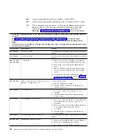
Follow
the
suggested
actions
in
the
order
in
which
they
are
listed
in
the
Action
column
until
the
problem
is
solved.
v
See
to
determine
which
components
are
customer
replaceable
units
(CRU)
and
which
components
are
field
replaceable
units
(FRU).
v
If
an
action
step
is
preceded
by
“(Trained
service
technician
only),”
that
step
must
be
performed
only
by
a
trained
service
technician.
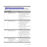
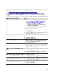
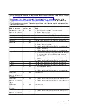
Error
code
Description
Action
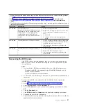
180-xxx-001
Failed
front
LED
panel
test.
1.
Reseat
the
operator
information
panel
cable.
2.
Replace
the
following
components
one
at
a
time,
in
the
order
shown,
restarting
the
server
each
time:
a.
Operator
information
panel
assembly
b.
(Trained
service
technician
only)
System
board
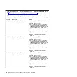
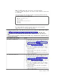
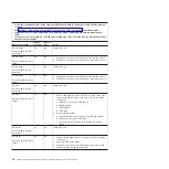
180-xxx-002
Failed
diagnostics
LED
panel
test.
Note:
The
Light
Path
diagnostics
panel
is
part
of
the
operator
information
panel
assembly.
1.
Reseat
the
operator
information
panel
cable.
2.
Replace
the
following
components
one
at
a
time,
in
the
order
shown,
restarting
the
server
each
time:
a.
Operator
information
panel
assembly
b.
(Trained
service
technician
only)
System
board
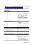
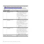
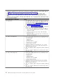
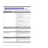
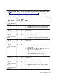
180-361-003
Failed
fan
LED
test.
1.
Reseat
the
fans.
2.
Replace
the
following
components
one
at
a
time,
in
the
order
shown,
restarting
the
server
each
time:
a.
Fans
b.
(Trained
service
technician
only)
System
board
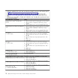
180-xxx-003
Failed
system
board
LED
test.
(Trained
service
technician
only)
Replace
the
system
board.
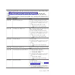
180-xxx-005
Failed
hard
disk
drive
backplane
LED
test.
1.
Reseat
the
following
components:
a.
Hard
disk
drive
backplane
cable
b.
Hard
disk
drive
backplane
2.
Replace
the
following
components
one
at
a
time,
in
the
order
shown,
restarting
the
server
each
time:
a.
Hard
disk
drive
backplane
b.
(Trained
service
technician
only)
System
board
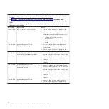
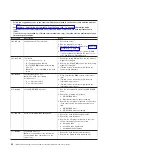
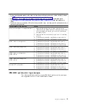
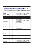
201-198-xxx
Memory
Test
Aborted.
1.
Restart
the
server.
2.
Run
the
diagnostic
test
again.
3.
Reinstall
the
diagnostic
programs
(see
4.
Check
the
system
event/error
log
and
the
BMC
log
for
messages
that
indicate
the
cause
of
the
error
and
take
the
indicated
action.
Chapter
3.
Diagnostics
65
Содержание 7985
Страница 1: ...IBM System x3655 Type 7985 and 7943 Problem Determination and Service Guide...
Страница 2: ......
Страница 3: ...IBM System x3655 Type 7985 and 7943 Problem Determination and Service Guide...
Страница 8: ...vi IBM System x3655 Type 7985 and 7943 Problem Determination and Service Guide...
Страница 18: ...xvi IBM System x3655 Type 7985 and 7943 Problem Determination and Service Guide...
Страница 36: ...18 IBM System x3655 Type 7985 and 7943 Problem Determination and Service Guide...
Страница 110: ...92 IBM System x3655 Type 7985 and 7943 Problem Determination and Service Guide...
Страница 112: ...View 1...
Страница 159: ...Battery Chapter 5 Removing and replacing server components 141...
Страница 202: ...184 IBM System x3655 Type 7985 and 7943 Problem Determination and Service Guide...
Страница 212: ...194 IBM System x3655 Type 7985 and 7943 Problem Determination and Service Guide...
Страница 217: ......
Страница 218: ...Part Number 42D2167 Printed in USA 1P P N 42D2167...

