background image

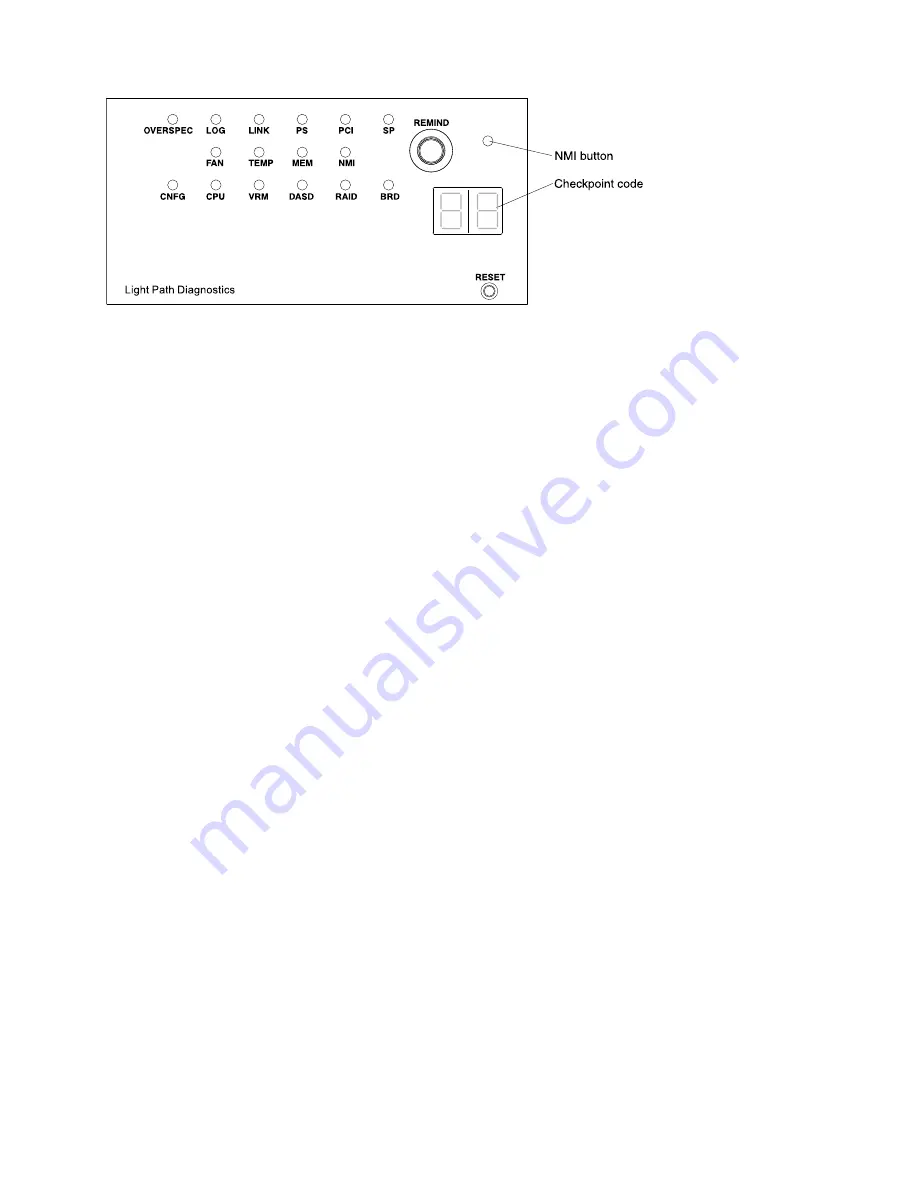
Figure 8. Light path diagnostics panel exposure

• 

Remind button: 

This button places the system-error LED on the front panel into Remind mode. In Remind 

mode, the system-error LED flashes every 2 seconds until the problem is corrected, the system is 
restarted, or a new problem occurs. By placing the system-error LED indicator in Remind mode, you 
acknowledge that you are aware of the last failure but will not take immediate action to correct the 
problem. The remind function is controlled by the IMM.

• 

NMI button: 

Press this button to force a nonmaskable interrupt to the microprocessor. It allows you to 

blue screen the server and take a memory dump (use this button only when directed by the IBM service 
support).

• 

Checkpoint code display: 

This display provides a checkpoint code that indicates the point at which the 

system stopped during the boot block and POST. A checkpoint code is either a byte or a word value that 
is produced by UEFI. The display does not provide error codes or suggest components to be replaced. 

• 

Reset button: 

Press this button to reset the server and run the power-on self-test (POST). You might have 

to use a pen or the end of a straightened paper clip to press the button. The Reset button is in the lower 
right-hand corner of the light path diagnostics panel.

For additional information about the light path diagnostics panel LEDs, see 

“Light path diagnostics LEDs” on 

page 17

.

Light path diagnostics LEDs

The following table describes the LEDs on the light path diagnostics panel and suggested actions to correct 

the detected problems.

Note:

Check the system-error log or system event log for additional information before replacing a FRU.

Chapter 1

.

The Lenovo System x3550 M3 server

17

Содержание 7944

Страница 1: ...System x3550 M3 Installation and User s Guide Machine Type 4254 and 7944...

Страница 2: ...mation document and the Safety Information and Environmental Notices and User Guide documents on the IBM Documentation CD Thirteenth Edition September 2023 Copyright Lenovo 2014 2023 LIMITED AND RESTR...

Страница 3: ...y 56 Installing a DIMM 57 Installing drives 58 Installing a hot swap hard disk drive 58 Installing a simple swap hard disk drive 59 Installing an optional DVD drive 61 Replacing a PCI riser card assem...

Страница 4: ...x A Getting help and technical assistance 123 Before you call 123 Using the documentation 124 Getting help and information from the World Wide Web 124 How to send DSA data 124 Creating a personalized...

Страница 5: ...n Ennen kuin asennat t m n tuotteen lue turvaohjeet kohdasta Safety Information Avant d installer ce produit lisez les consignes de s curit Vor der Installation dieses Produkts die Sicherheitshinweise...

Страница 6: ...English language caution or danger statement with translated versions of the caution or danger statement in the Safety Information document For example if a caution statement is labeled Statement 1 tr...

Страница 7: ...s as described in the following table when installing moving or opening covers on this product or attached devices To Connect To Disconnect 1 Turn everything OFF 2 First attach all cables to devices 3...

Страница 8: ...ents or performance of procedures other than those specified herein might result in hazardous radiation exposure DANGER Some laser products contain an embedded Class 3A or Class 3B laser diode Note th...

Страница 9: ...d of the power cord that is connected to the device you must connect the other end of the power cord to an easily accessible power source Statement 8 CAUTION Never remove the cover on a power supply o...

Страница 10: ...R Always lower the leveling pads on the rack cabinet Always install stabilizer brackets on the rack cabinet Always install servers and optional devices starting from the bottom of the rack cabinet Alw...

Страница 11: ...ceability on page 12 You can obtain up to date information about the server and other IBM server products at http www ibm com systems x At http www ibm com support mysupport you can create a personali...

Страница 12: ...l drive bay If firmware and documentation updates are available you can download them from the IBM Web site The server might have features that are not described in the documentation that comes with t...

Страница 13: ...obat Reader 3 0 or later or xpdf which comes with Linux operating systems Using the Documentation Browser Use the Documentation Browser to browse the contents of the CD read brief descriptions of the...

Страница 14: ...format on the IBMDocumentation CD It contains translated environmental notices IBM License Agreement for Machine CodeThis document is in PDF format on the IBMDocumentation CD It provides translated v...

Страница 15: ...ng statement in your language in the Safety Information document The following notices and statements are used in this document Note These notices provide important tips guidance or advice Important T...

Страница 16: ...connected at the same time Note The maximum video resolution is 1600 x 1200 at 75 Hz SVGA compatible video controller DDR2 250 MHz SDRAM video memory controller Avocent Digital Video Compression 16 MB...

Страница 17: ...nal RAID 6 60 and SED upgrade An optional ServeRAID M5015 SAS SATA adapter that provides RAID levels 0 1 5 10 and 50 with optional RAID 6 60 and SED upgrade Size 1U Height 43 mm 1 7 inches Depth 711 m...

Страница 18: ...wer level of the computer See Acoustical noise emissions Test voltage and frequency 230V 50 Hz or 60 Hz Total harmonic distortion of the electricity supply system The maximum harmonic content of the i...

Страница 19: ...apters Note The server does not support DOS Disk Operating System IBM Dynamic System Analysis Preboot diagnostics programs The Dynamic System Analysis DSA Preboot diagnostics programs are stored on th...

Страница 20: ...stem memory capacity The memory bus supports up to 192 GB of system memory when registered DIMMs are installed The server supports up to 48 GB if unbuffered DIMMs are installed The memory controller s...

Страница 21: ...hot swap power supplies and six dual motor hot swap fans which provide redundancy and hot swap capability for a typical configuration The redundant cooling by the fans in the server enables continued...

Страница 22: ...or module failure identification through light path diagnostics Memory mirroring support memory mirroring are mutually exclusive of each other Parity checking on the small computer system interface SC...

Страница 23: ...otifying users of problems that occur on systems and the ability to isolate the sources of the problems Notifying users when systems need updates and distributing and installing updates on a schedule...

Страница 24: ...w simple swap HDD model Rack release latches Press the latches on each front side of the server to remove the server from the rack Hard disk drive activity LEDs This LED is used on hot swap SAS or SAT...

Страница 25: ...e power control button to turn on the server Lit The server is turned on Fading on and off The server is in a reduced power state To wake the server press the power control button or use the IMM web i...

Страница 26: ...l slide the blue release latch on the operator panel to the left Pull forward on the panel until the hinge of the operator panel is free of the server chassis Then pull down on the panel so that you c...

Страница 27: ...des a checkpoint code that indicates the point at which the system stopped during the boot block and POST A checkpoint code is either a byte or a word value that is produced by UEFI The display does n...

Страница 28: ...use one of the following procedures If the 12 V channel A error LED is lit complete the following steps 1 Turn off the server and disconnect the power from the server 2 Remove the optical drive fans...

Страница 29: ...rd switches and jumpers on page 36 for the location of the SW4 switch block on the system board 3 Restart the server to see whether the problem remains 4 Reinstall each device that you removed in step...

Страница 30: ...ny failing device 6 Trained service technician only Replace the system board If the 12 V AUX channel error LED is lit complete the following steps 1 Turn off the server and disconnect the power from t...

Страница 31: ...the failing adapter by using the LEDs and the information in the system error log remove one adapter at a time from the failing PCI bus and restart the server after each adapter is removed 4 Replace t...

Страница 32: ...vents are not blocked 5 For more information go to http www ibm com support entry portal docdisplay lndocid SERV CALL MEM When only the MEM LED is lit a memory error has occurred When both the MEM an...

Страница 33: ...3 If the CNFG LED and the PS LED are lit the system issues an invalid power configuration error Make sure that both power supplies installed in the server are of the same type CPU An invalid microproc...

Страница 34: ...disk drive backplane 5 If the error remains replace the following components one at a time in the order listed restarting the server after each a Replace the hard disk drive b Replace the hard disk dr...

Страница 35: ...video resolution is 1600 x 1200 at 75 Hz Serial connector Connect a 9 pin serial device to this connector The serial port is shared with the integrated management module IMM The IMM can take control o...

Страница 36: ...ower to the system During typical operation both the ac and dc power LEDs are lit For any other combination of LEDs see Power supply LEDs on page 27 OUT OK power LED Each hot swap dc power supply has...

Страница 37: ...AID SAS SATA controller AC power supply LEDs Use this information to view AC power supply LEDs The following illustration shows the location of the AC power supply LEDs on the rear of the server See t...

Страница 38: ...ly 2 If a power channel error LED on the system board is not lit replace the power supply see the documentation that comes with the power supply for instructions 3 If a power channel error LED on the...

Страница 39: ...wer source Replace the power supply see the documentation that comes with the power supply for instructions Off On Off Faulty power supply Replace the power supply Off On On Faulty power supply Replac...

Страница 40: ...dicates that IMM is fully operational You can now press the power control button to power on the server 4 If this LED does not blink within 30 seconds of connecting a power source to the server comple...

Страница 41: ...is information to turn off the server When you turn off the server and leave it connected to power the server can respond to requests from the service processor such as a remote request to turn on the...

Страница 42: ...you remove the PCI Express riser assembly and the PCI X riser assembly Otherwise this will cause the active power management event signal to become disabled by the system board logic and Wake on LAN...

Страница 43: ...d logs see How to send DSA data on page 33 4 To ship the server repackage it in the original undamaged packing material and observe IBM procedures for shipping Support information for IBM Business Par...

Страница 44: ...Figure 14 Server components 34 System x3550 M3Installation and User s Guide...

Страница 45: ...tration shows the internal connectors on the system board Figure 15 System board internal connectors System board external connectors The following illustration shows the external connectors on the sy...

Страница 46: ...pers The following illustration shows the location and description of the switches and jumpers Note If there is a clear protective sticker on the top of the switch blocks you must remove and discard i...

Страница 47: ...SW4 switch block SW3 switch block uEFI boot recovery jumper J29 IMM recovery jumper J147 Figure 17 System board switches and jumpers Chapter 2 Installing optional devices 37...

Страница 48: ...ns 2 and 3 before the server is turned on alters which flash ROM page is loaded Do not change the jumper pin position after the server is turned on This can cause an unpredictable problem The followin...

Страница 49: ...On and then Off you force a power on which overrides the power on and power off button on the server and they become nonfunctional 3 Off Trained service technician only Forced power permission Changi...

Страница 50: ...Figure 18 System board LEDs System board optional device connectors The following illustration shows the connectors for user installable options 40 System x3550 M3Installation and User s Guide...

Страница 51: ...y on page iii the guidelines in Working inside the server with the power on on page 43 and Handling static sensitive devices on page 43 This information will help you work safely Make sure that the de...

Страница 52: ...rical outlets for the server monitor and other devices Back up all important data before you make changes to disk drives Have a small flat blade screwdriver a small Phillips screwdriver and a T8 torx...

Страница 53: ...designed to operate safely while it is turned on and the server cover is removed Follow these guidelines when you work inside a server that is turned on Avoid wearing loose fitting clothing on your fo...

Страница 54: ...he cable connection and connectors The following illustration shows the internal routing and connectors for the two SAS signal cables in server models with eight drive bays Notes 1 To connect the SAS...

Страница 55: ...ator information panel cable slightly press the cable toward the chassis then pull to remove the cable from the connector on the system board Pulling the cable out of the connector by excessive force...

Страница 56: ...o cable is routed under the video cable and then both the USB and video cables are routed under the cable retention tab and the top cover latch receptacle To remove the USB video cable slightly press...

Страница 57: ...al routing for the SATA power cable and signal cable Figure 24 Simple swap backplate assembly cable connection The following illustration shows the internal routing for the SATA power cable the SATA s...

Страница 58: ...41 Step 2 Turn off the server and peripheral devices and disconnect the power cords and all external cables if necessary Note When you disconnect the power source from the server you lose the ability...

Страница 59: ...low replace the server cover before you turn on the server Removing the DIMM air baffle Use this information to remove the DIMM air baffle To remove the DIMM air baffle complete the following steps St...

Страница 60: ...fle complete the following steps Step 1 Read the safety information that begins on Safety on page iii and Installation guidelines on page 41 Step 2 Turn off the server and peripheral devices and disco...

Страница 61: ...nous dynamic random access memory SDRAM dual inline memory modules DIMMs with error correcting code ECC See http www ibm com supportportal for a list of supported memory modules for the server The spe...

Страница 62: ...e microprocessor DIMM speed and the number of DIMMs installed in each channel In two DIMM per channel configuration a server with an Intel Xeon X5600 series microprocessor automatically operates with...

Страница 63: ...usable memory is reduced depending on the system configuration A certain amount of memory must be reserved for system resources To view the total amount of installed memory and the amount of configur...

Страница 64: ...installation sequence Installed microprocessor DIMM connector population sequence Microprocessor socket 1 3 6 9 2 5 8 1 4 7 Microprocessor socket 2 12 15 18 11 14 17 10 13 16 Memory mirroring Memory...

Страница 65: ...connectors 1 on channel 0 and DIMM connector 2 on channel 1 DIMM connectors 3 6 9 12 15 and 18 on channel 2 are not used in memory mirroring mode CH0 CH1 CH2 CPU1 1 1 2 2 3 3 3 6 2 1 5 4 8 7 CH2 CH0 C...

Страница 66: ...memory mirroring in the Setup utility see Using the Setup utility on page 106 When you use the memory online spare feature consider the following information The memory online spare feature is suppor...

Страница 67: ...f the server and peripheral devices and disconnect the power cords and all external cables if necessary Step 3 Remove the cover see Removing the cover on page 48 Step 4 Open the retaining clip on each...

Страница 68: ...optional ultra slim SATA optical drive Check the instructions that come with the drive to determine whether you have to set any switches or jumpers on the drive If you are installing a SAS or SATA har...

Страница 69: ...e ServeRAID adapter documentation for additional information about RAID operation and complete instructions for using the ServeRAID adapter Step 5 If you are installing additional hot swap hard disk d...

Страница 70: ...le swap models of the server do not support the Hypervisor USB flash device and the installation of the SAS SATA riser card is not supported The simple swap server models are available only in non RAI...

Страница 71: ...f your server does not come with a DVD drive bay you can purchase and install the optical drive cage and bezel option The option includes the components that allow you to install an optional DVD drive...

Страница 72: ...o not remove the covers Removing the covers of the laser product could result in exposure to hazardous laser radiation There are no serviceable parts inside the device Use of controls or adjustments o...

Страница 73: ...ge and place it on a static protective surface Step 7 Follow the instructions that come with the DVD drive to set any jumpers or switches Step 8 Attach the drive retention clip that you removed from t...

Страница 74: ...the following steps Step 1 Read the safety information that begins on Safety on page iii and Installation guidelines on page 41 Step 2 Turn off the server and peripheral devices and disconnect the po...

Страница 75: ...PCI riser card assembly see Installing an adapter on page 66 Step 9 Set any jumpers or switches on the adapter as directed by the adapter manufacturer Step 10 If you are installing the PCI riser card...

Страница 76: ...M5015 adapter comes installed on some models of the server You can replace the IBM ServeRAID SAS SATA adapter with an optional IBM ServeRAID SAS SATA adapter in the slot For configuration information...

Страница 77: ...ull height half length adapters The following table lists the supported configurations for the PCI riser card slot Table 14 PCI riser slots supported configurations PCI riser card slot number Configur...

Страница 78: ...ter Figure 42 Adapter installation Step 6 Install the riser card assembly in the server see Replacing a PCI riser card assembly on page 64 Step 7 Perform any configuration tasks that are required for...

Страница 79: ...PCI riser card assembly installed in slot 2 You can replace a PCI X riser card assembly with a PCI Express riser card assembly To replace a PCI X riser card assembly with a PCI Express riser card ass...

Страница 80: ...ff all external cables and power cords are disconnected and the cover has been removed Step 3 If you are installing a new or replacement SAS SATA adapter touch the static protective package that conta...

Страница 81: ...tem board Figure 45 ServeRAID controller installation Step 7 Route the signal cables from the drive backplane over the blue adapter retention bracket Step 8 Connect the signal cables to the SAS SATA a...

Страница 82: ...backplane for drive bays 4 through 7 and connect it to the ServeRAID adapter connector that is closest to the power supply cage Connect the other signal cable so that is attached to the drive backpla...

Страница 83: ...o the other connector on the adapter Figure 49 ServeRAID M10i adapter cable connection If you have other devices to install or remove do so now Otherwise go to Completing the installation on page 100...

Страница 84: ...Remove the cover see Removing the cover on page 48 Step 4 Align the upgrade key with the connector on the ServeRAID adapter and push it into the connector until it is firmly seated Figure 50 ServeRAID...

Страница 85: ...ling fans Attention To ensure proper operation replace a failed hot swap fan within 30 seconds To install an additional hot swap fan complete the following steps Step 1 Read the safety information tha...

Страница 86: ...installation Step 5 Insert the fan into the fan slot in the fan assembly bracket and press it down until it is seated correctly in the slot and the fan connector is seated correctly in the connector o...

Страница 87: ...r you must install an additional power supply The server automatically shuts down if the total power consumption exceeds the total power supply output capacity You can enable the power capping feature...

Страница 88: ...one of these parts contact a service technician To install a hot swap power supply complete the following steps Step 1 Read the safety information that begins on Safety on page iii and Installation gu...

Страница 89: ...power cord to a properly grounded electrical outlet Step 8 Make sure that the ac power LED and the dc power LED on the ac power supply are lit indicating that the power supply is operating correctly T...

Страница 90: ...til it is seated firmly Figure 56 USB embedded hypervisor flash device installation If you have other devices to install or remove do so now Otherwise go to Completing the installation on page 100 Ins...

Страница 91: ...p 1 Read the safety information that begins on Safety on page iii and Installation guidelines on page 41 Step 2 Turn off the server and peripheral devices and disconnect the power cords Step 3 Remove...

Страница 92: ...n the rear of the chassis if it has not been removed already Figure 59 Filler panel removal Step 7 Install the two standoffs on the system board Step 8 Insert the bottom tabs of the metal clip into th...

Страница 93: ...er line up with the port openings on the chassis Figure 61 Adapter installation Step 12 Slide the port connectors on the adapter into the port openings on the chassis then press the adapter firmly unt...

Страница 94: ...server and peripheral devices and disconnect the power cords Step 3 Remove the cover see Removing the cover on page 48 Note Step 4 to Step 5 apply to a RAID adapter that is already installed in the s...

Страница 95: ...dapter a Remove the interposer card and the screw from the bag b Rotate the plastic standoff on the interposer card so that it aligns with the hole on the RAID adapter then align the connector on inte...

Страница 96: ...om the bag and tighten the screw to secure the interposer card to the RAID adapter Step 8 Connect one end of the remote batter cable to the interposer card Attention To avoid damage to the hardware ma...

Страница 97: ...in the server see Replacing a PCI riser card assembly on page 64 Step 10 Route the remote battery cable as shown in the illustration depending on the PCI slot in which the RAID adapter is installed Re...

Страница 98: ...d of the remote battery cable to the remote battery cable connector on the battery carrier Attention To avoid damage to the hardware make sure that the black dot on the remote battery cable connector...

Страница 99: ...erneath the other tab while pressing release tab toward the front of the server then press it down until it snaps in place to hold the battery carrier firmly in place If you have other devices to inst...

Страница 100: ...he bezel Bezel screws Video connector screws Figure 71 Screws removal Step 6 Remove the screws from the video connector Step 7 Pull the top of the bezel out slightly then rotate it downward until the...

Страница 101: ...u slide the cable connector to the left then slide the cable connector latch down to lock the cable in place Figure 73 DVD drive cable installation Step 13 Connect the other end of the DVD cable to th...

Страница 102: ...rder a SAS SATA 4 Pac HDD option contact your IBM sales representative or IBM reseller The SAS SATA 4 Pac HDD option kit contains the following components One 2 5 inch hard disk drive backplane with b...

Страница 103: ...cage forward into the server until the screw holes on the drive cage align with the screw holes on the chassis Bezel Hard disk drive cage Figure 76 Hard disk drive cage installation Step 9 Insert the...

Страница 104: ...able to the connector on the SAS SATA adapter see Step 8 in Installing a ServeRAID SAS SATA controller on the SAS SATA RAID riser card Step 15 Reinstall the hard disk drives and filler panels If you h...

Страница 105: ...all the microprocessor with lowest stepping level and features in microprocessor socket 1 Both microprocessor voltage regulator modules are integrated on the system board If you have to replace a micr...

Страница 106: ...evices see Handling static sensitive devices on page 43 Figure 78 Dust cover removal c Locate the microprocessor installation tool that comes with the new microprocessor Note The microprocessor instal...

Страница 107: ...val f Carefully align the microprocessor installation tool over the microprocessor socket Attention The microprocessor fits only one way on the socket You must place a microprocessor straight down on...

Страница 108: ...t sink on top of the microprocessor with the thermal grease side down Attention Do not touch the thermal grease on the bottom of the heat sink after you remove the plastic cover Touching the thermal g...

Страница 109: ...ssor Notes Read the safety information that begins on Safety on page iii Read the Installation guidelines on page 41 Read Handling static sensitive devices on page 43 To replace damaged or contaminate...

Страница 110: ...e Updating the server configuration on page 103 Step 6 Slide the server back into the rack if necessary Step 7 Start the server Confirm that it starts correctly and recognizes the newly installed devi...

Страница 111: ...e complete the following steps Step 1 Align the DIMM air baffle over the DIMMs so that the baffle pin on the left side of the air baffle aligns with the pin hole next to DIMM connector 8 on the system...

Страница 112: ...move the cover later Step 2 Position the cover on top of the server Tab Cover Figure 89 Cover installation Step 3 Slide the cover toward the front of the server Step 4 Make sure that the cover correct...

Страница 113: ...changed The Setup utility starts automatically so that you can save the new configuration settings Some optional devices have device drivers that you must install For information about installing dev...

Страница 114: ...104 System x3550 M3Installation and User s Guide...

Страница 115: ...software that enables multiple operating systems to run on a host system at the same time For more information about using the embedded hypervisor see Using the embedded hypervisor on page 116 Remote...

Страница 116: ...Setup utility Use these instructions to start the Setup utility Use the Unified Extensible Firmware Interface UEFI formerly BIOS Setup utility to perform the following tasks View configuration inform...

Страница 117: ...rts Select this choice to view or change assignments for devices and input output I O ports You can configure the serial ports configure remote console redirection enable or disable integrated Etherne...

Страница 118: ...LAN hardware and software and the operating system supports Wake on LAN functions you can specify a startup sequence for the Wake on LAN functions For example you can define a startup sequence that c...

Страница 119: ...n the settings you are asked whether you want to save the changes or exit without saving them Passwords From the User Security menu choice you can set change and delete a power on password and an admi...

Страница 120: ...er on password switch enable switch 1 of the system board switch block SW4 to bypass the power on password check see Table 8 System board SW4 switch block definition on page 39 for more information SW...

Страница 121: ...equence that is set in the Setup utility Starting the backup server firmware The system board contains a backup copy area for the server firmware This is a secondary copy of the server firmware that y...

Страница 122: ...tem date and time Detects the RAID adapter or controller and runs the SAS SATA RAID configuration program Checks the microcode firmware levels of a ServeRAID adapter and determines whether a later lev...

Страница 123: ...presents operating system partition options that are based on your operating system selection and the installed hard disk drives 4 The ServerGuide program prompts you to insert your operating system...

Страница 124: ...e Command line interface Configuration save and restore PCI configuration data Boot sequence manipulation The IMM also provides the following remote server management capabilities through the OSA SMBr...

Страница 125: ...the cause of the hang condition Enabling the remote presence feature Use this information to enable the remote presence feature To enable the remote presence feature complete the following steps Step...

Страница 126: ...at is provided The IMM will log you off of the Web interface if your browser is inactive for the number of minutes that you entered for the timeout value Step 4 Click Continue to start the session The...

Страница 127: ...can use it to configure the network as a startable device and you can customize where the network startup option appears in the startup sequence Enable and disable the Broadcom Gigabit Ethernet Utili...

Страница 128: ...enhanced array of three to eight disks including up to two optional hot spares All data on the array disks will be deleted Integrated Striping IS also known as RAID 0 Use this option to create an inte...

Страница 129: ...t use the Up Arrow and Down Arrow keys To scroll left and right use the Left Arrow and Right Arrow keys or the End key Press Alt D Step 5 To start the low level formatting operation select Format and...

Страница 130: ...management director downloads html b If a newer version of Systems Director than what comes with the server is shown in the drop down list follow the instructions on the web page to download the lates...

Страница 131: ...tep 10 Return to the Welcome page of the Web interface and click View updates Step 11 Select the updates that you want to install and click Install to start the installation wizard The UpdateXpress Sy...

Страница 132: ...122 System x3550 M3Installation and User s Guide...

Страница 133: ...d solution within a software upgrade If you have installed new hardware or software in your environment check http www ibm com systems info x86servers serverproven compat us to make sure that the hard...

Страница 134: ...em products http pic dhe ibm com infocenter flexsys information index jsp System x products http www ibm com systems x NeXtScale System products http pic dhe ibm com infocenter nxtscale documentation...

Страница 135: ...o to provide warranty service go to http www ibm com partnerworld and click Business Partner Locator For IBM support telephone numbers see http www ibm com planetwide In the U S and Canada call 1 800...

Страница 136: ...126 System x3550 M3Installation and User s Guide...

Страница 137: ...blication Lenovo may make improvements and or changes in the product s and or the program s described in this publication at any time without notice The products described in this document are not int...

Страница 138: ...all hard disk drive bays with the largest currently supported drives that are available from Lenovo Maximum memory might require replacement of the standard memory with an optional memory module Each...

Страница 139: ...culate The room air must be continuously filtered with 40 atmospheric dust spot efficiency MERV 9 according to ASHRAE Standard 52 21 Air that enters a data center must be filtered to 99 97 efficiency...

Страница 140: ...Industrie Canada Cet appareil num rique de la classe A est conforme la norme NMB 003 du Canada Australia and New Zealand Class A statement Attention This is a Class A product In a domestic environmen...

Страница 141: ...ch f r die Konformit tserkl rung nach Paragraf 5 des EMVG ist die Lenovo Deutschland GmbH Gropiusplatz 10 D 70563 Stuttgart Informationen in Hinsicht EMVG Paragraf 4 Abs 1 4 Das Ger t erf llt die Schu...

Страница 142: ...n 20 A per phase Korea Communications Commission KCC statement This is electromagnetic wave compatibility equipment for business Type A Sellers and users need to pay attention to it This is for any ar...

Страница 143: ...ecting cables 102 connector Ethernet 24 Ethernet systems management 24 power supply 24 serial 24 USB 14 24 video front 14 rear 24 connectors external 35 internal 35 internal cable routing 44 option 40...

Страница 144: ...ve installing 2 5 inch 58 hot swap drive SAS SATA IDs 59 hot swap hard disk drive cage installing 92 humidity 5 hypervisor flash device installing 80 I IBM Advanced Settings Utility program overview 1...

Страница 145: ...uence 54 56 memory online spare description 56 memory support 8 menu choices Setup utility 107 microprocessor 8 installing 94 specifications 5 microprocessor 2 air baffle installing 100 removing 50 mi...

Страница 146: ...8 working inside with the power on 43 Server power features 30 server components 33 server configuration updating 103 server backup firmware starting 111 ServeRAID adapter removing 70 ServeRAID adapte...

Страница 147: ...States FCC Class A notice 130 UpdateXpress 13 121 updating server configuration 103 Systems Director 120 USB connector 14 24 using embedded hypervisor 116 IMM 113 integrated management module 113 LSI...

Страница 148: ...138 System x3550 M3Installation and User s Guide...

Страница 149: ......

Страница 150: ...Part Number 00KC032 Printed in China 1P P N 00KC032 1P00KC032...

Отзывы: