background image

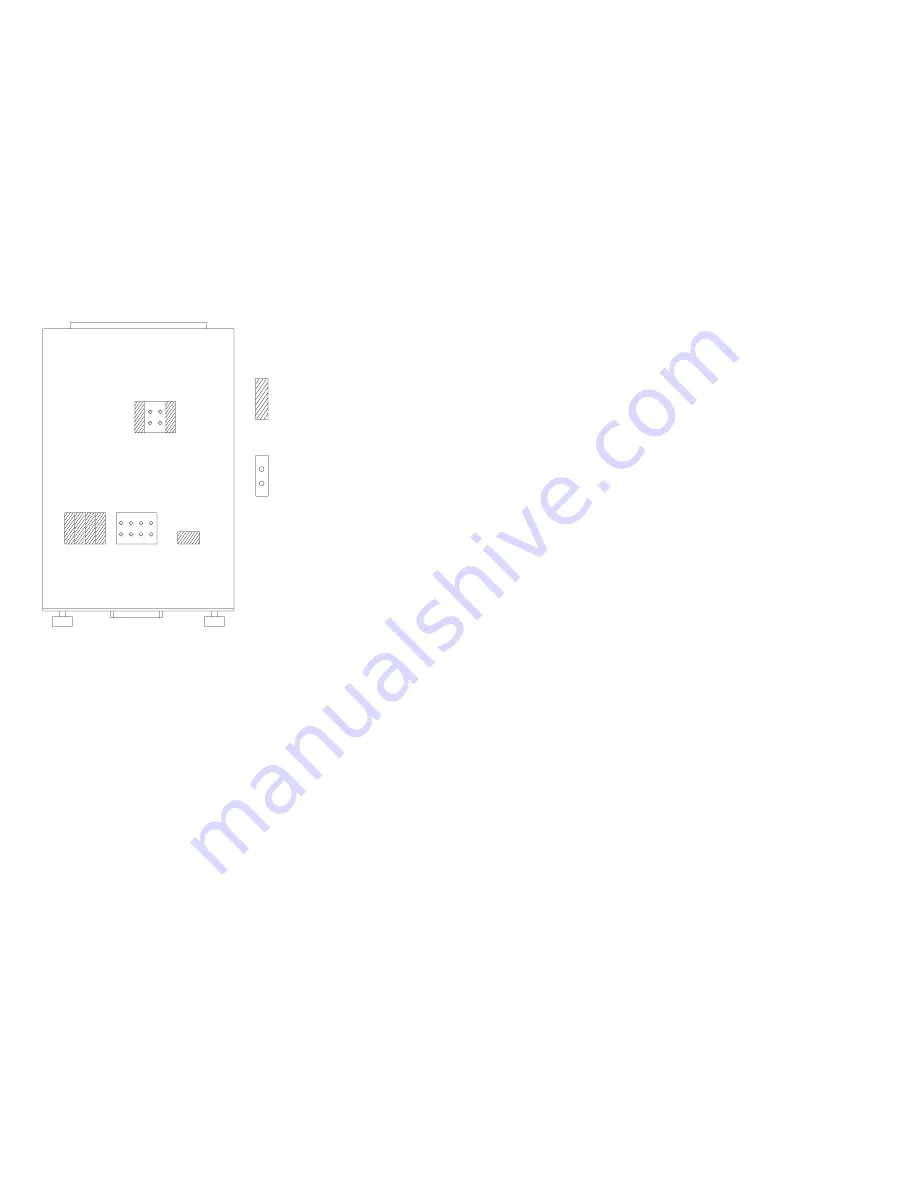
Serial card jumper locations

Jumper Installed

No Jumper Installed

E90APC13

The 4247 Model V03 can also connect to a host using the serial
attachment feature.

Shown here is the location of the jumpers that are mounted on to
the serial card. These must be in the correct location for the
proper operation of the serial interface. Do not move these
jumpers. Replace the card if required.

Chapter 5. Removals, service checks and adjustments

205

Содержание 4247-V03

Страница 1: ...IBM 4247 Model V03 Serial Matrix Impact Printer IBM 4247 Model V03 Maintenance Information Part Number 75P1301 IBM ...

Страница 2: ...dition applies to release one of IBM 4247 Model V03 Maintenance Information and to all subsequent releases and modifications until otherwise indicated in new editions Copyright International Business Machines Corporation 2002 All rights reserved US Government Users Restricted Rights Use duplication or disclosure restricted by GSA ADP Schedule Contract with IBM Corp ...

Страница 3: ...pter 3 Wiring diagrams Chapter 4 Locations Chapter 5 Removals service checks and adjustments Chapter 6 Parts catalog Chapter 7 Preventative Maintenance Appendix A Printer configuration Appendix B Supplies forms paths environmental considerations Appendix C Flashing memory Notices Copyright IBM Corp 2002 3 ...

Страница 4: ... receptacle 8 Electrical safety and portable power strip receptacles 8 Connecting or disconnecting a communication port a teleport or an attachment connector 9 Servicing during an electrical storm 9 Safety inspection 10 Instructions 10 Reference items 10 Safety inspection procedure 10 Performing a power receptacle safety check 11 Ground connectors check 12 Environmental notices 15 Product recyclin...

Страница 5: ...in IBM 4247 Model V03 Safety Information G544 5862 Example of a Danger notice DANGER 1 10 Hazardous voltages are present Do not touch the pins or sockets of the power receptacle Caution hazard level The word Caution indicates the presence of a hazard that has the potential of causing moderate or minor personal injury CAUTION notices are numbered 2 1 2 2 and so forth where they appear in the text o...

Страница 6: ...ing laboratory indicates that the product is designed and manufactured in accordance with national requirements intended to minimize safety hazards IBM equipment meets a very high standard of safety in design and manufacture Remember however that this product operates under conditions of high electrical potentials and heat generation both of which are functionally necessary Because the paper used ...

Страница 7: ...not touch any components pins or connectors If possible keep one hand on the frame while you are installing or removing an ESD sensitive part v Do not place an ESD sensitive part on anything that can provide a discharge path from your body through the ESD sensitive part If you need to put down the ESD sensitive part first put it into the ESD protective wrapper in which it was shipped v Prevent ESD...

Страница 8: ...rd and plug Ensure that you have the correct power cord and plug Use this cord and plug only with an approved correctly installed power receptacle Electrical safety and portable power strip receptacles Extension cords DANGER 1 12 Do not use an extension power cord The customer must supply the correct electrical outlet which must meet the requirements stated under Approved power cord and receptacle...

Страница 9: ...and unplug the printer power cord before connecting or disconnecting a communication port a teleport or other attachment connector Servicing during an electrical storm DANGER 1 13 Do not connect or disconnect a communication port a teleport or any other connector during an electrical storm Safety and environmental notices 9 ...

Страница 10: ...nnections can cause serious electrical shock v Mechanical A missing safety cover or shield is hazardous Moving parts such as gears shaft and pulleys are hazardous v Chemical Use only approved cleaning agents Do not use other solvents or chemicals Reference items You will need the following items v A copy of the machine EC history v A list of current safety ECs v IBM Electrical Safety for IBM Custo...

Страница 11: ...ng contamination water or other liquids or signs of fire or smoke damage 9 Check for worn frayed or pinched cables Performing a power receptacle safety check A trained service representative or a qualified electrician should perform all checks necessary to ensure safe operation These should include the following checks and any other required by local regulations v Check the ac voltage at all assoc...

Страница 12: ...ctrical outlet and any temporary power tap must meet the requirements as stated in 4247 Model V03 nominal ac input power requirements Attention Inform the customer if the voltages are not within the correct operating range to allow correction before the equipment is plugged in and operated For pluggable equipment the socket outlet shall be installed near the equipment and shall be easily accessibl...

Страница 13: ...sensor Front Tractor paper present sensor Rear Tractor paper present sensor 38V 5V Front Tractor paper run sensor Rear Tractor paper run sensor Control Panel Assembly Attention Light GND 38V Parallel I F GND 5V CHASSIS GND Paper Feed Stepper Motor 38V AC Power 38V 5V 15 1 I O On Off Switch SW1 P3 WR1 WR2 Line 2 Neutral Line 1 AC IN choke choke CHASSIS GND POWER SUPPLY BOARD GND GND P1 P2 GND 24V F...

Страница 14: ...Ground path illustrations e61a6003 Left Side Adapter Card AC Input Right Side Right Side Printer to Metal Table 1 2 4 5 3 6 1 6 See previous page for wiring diagram Safety and environmental notices 14 ...

Страница 15: ...recycle their equipment when it is no longer needed IBM offers a variety of programs and services to assist equipment owners in recycling their IT products Information on these product recycling offerings can be found on IBM s Internet site at http www ibm com ibm environment products prp shtml Safety and environmental notices 15 ...

Страница 16: ...the second path is an optional feature The printer operator panel is common with the Models 001 002 and 003 and includes the same full function full size 2 line by 40 character display making messages and menus easy to understand Print quality choices are Fast Draft mode DP mode DP DP Text mode DP Text and Near Letter Quality mode NLQ Versatile paper handling capability provides printing on up to ...

Страница 17: ...he second optional tractor is the front tractor and the base tractor becomes the rear tractor Print qualities Fast Draft is a new print quality for the IBM 4247 Model V03 that is available only on the 4247 Model V03 The Data Processing DP Data Processing Text DP Text Near 2 Letter Quality NLQ OCR A and OCR B print qualities on the 4247 Model V03 are equivalent in character size shape and resolutio...

Страница 18: ...racter cell size dots Fast Draft 45 72 9 9 DP 60 72 12 9 DP Text 100 144 20 9 NLQ 100 144 20 18 4247 Model V03 differences and commonality with earlier models Adjustments All 4247 Model V03 adjustments are common to earlier models with just a few minor differences for example carriage belt tension has been increased for the wider 4247 Model V03 carriage belt Attachment cards The 4247 Model V03 att...

Страница 19: ...rs were found on earlier models Flash memory download and printer microcode file The 4247 Model V03 flash download code is a single file that supports all printer attachment configurations The download program which can be executed from a DOS command window from any computer sends code to the printer through the parallel port Flash download code is available on the IBM First database and is also a...

Страница 20: ...lso have a 12 pin ribbon cable plugged into it This connector and cable are not used by the 4247 Model V03 18 wire print head AFTA service check and adjustment procedures for the V03 are common with earlier models Printhead mask The 4247 Model V03 print head mask is a new easy change metal spring attached to the carriage by two easy access screws Ribbon cartridge The 4247 Model V03 ribbon is speci...

Страница 21: ...h S544 5861 75P0513 IBM 4247 Model V03 Programming s Reference S544 5864 IBM 4247 Model V03 User s Guide S544 5863 v IBM 4247 Model V03 Maintenance Information CD SK2T 9360 75P0796 Contents of CD ROM This CD ROM is not packaged with the printer IBM 4247 Model V03 Safety Information G544 5862 75P0512 IBM 4247 Model V03 Quick Setup Guide English IBM 4247 Model V03 User s Guide S544 5863 IBM 4247 Mod...

Страница 22: ...7 Model V03 Quick Setup Guide English Danish Dutch Finnish Swedish S544 5860 75P0514 v IBM 4247 Model V03 Quick Setup Guide English Arabic S Chinese Hungarian Polish Russian Turkish S544 5861 75P0513 Preface 22 ...

Страница 23: ...p cover interlock 61 MAP 0190 Form feed problems 62 MAP 0200 55 AFTA errors 73 MAP 0210 Intermittent failures 75 MAPs reference tables 77 Reference table 1 error messages 77 Reference table 2 no printed characters 85 Reference table 3 print quality failures 86 Reference table 4 operator panel and miscellaneous problems 87 Reference table 5 LED and test page problems LAN attachment card 88 Referenc...

Страница 24: ...Reference table 8 ribbon lift and 26 pin cable connectors 93 Chapter 1 Diagnosing problems 24 ...

Страница 25: ...y quickly identify problem areas v The normal place to start a service call in these MAPs is at MAP 0100 START OF CALL MAP 0100 START OF CALL This MAP sends you to a Field Replaceable Unit FRU or to another MAP that is indicated by the symptoms If you bypass MAP 0100 START OF CALL and start the service with another MAP you may be using the wrong MAP The questions in that MAP may not refer to your ...

Страница 26: ...ble the MAPs are written so that No is the error path answer v Verify repair or exchange FRU When a card or a cable is identified as the failing FRU reseat it and verify that the same problem remains If the problem continues exchange the FRU Start again at MAP 0100 START OF CALL see MAP 0100 START of call to ensure the correct operation of the printer before returning it to the customer Intermitte...

Страница 27: ...est and diagnostic IPDS Intelligent Printer Data Stream SCS SNA systems network architecture character string FRU Field replaceable unit ESD Electrostatic discharge NPS Network printer server ACGA Attachment card guide assembly Chapter 1 Diagnosing problems 27 ...

Страница 28: ...s No 1 Has the Customer completed the Problem Solving Procedures in the IBM 4247 Model V03 User s Guide Go to step 2 Attempt recovery using the Problem Solving Procedures in IBM 4247 Model V03 User s Guide Go to step 2 as needed 2 Does the printer display a message Go to Reference table 1 error messages Note This table does not list all the messages that might appear in the display such as informa...

Страница 29: ...n Reference table 2 no printed characters and perform the action suggested Go to step 4 4 Is the problem print quality Find the description of the failure in Reference table 3 print quality failures and perform the action suggested Find the description of the failure in Reference table 4 operator panel and miscellaneous problems and perform the action suggested Chapter 1 Diagnosing problems 29 ...

Страница 30: ...nfiguration Notes 1 This is the correct MAP for a Model V03 with parallel only or a Model V03 with a serial attachment card 2 Printing in hexadecimal code is available to aid service personnel and programmers for host program debug On the operator panel press the Hex Print key Refer to IBM 4247 Model V03 User s Guide for instructions 3 A computer such as a laptop can be connected to the printer pa...

Страница 31: ...les through the options found by pressing the Menu key the Configuration Menu should appear Table 2 Configuration Menu Parallel and Serial Configuration This is an indication that the printer recognizes the serial card v When data is received on the serial port and printing begins the display will change to Serial Chapter 1 Diagnosing problems 31 ...

Страница 32: ... a teleport or any other connector during an electrical storm DANGER 1 14 Switch off printer power and unplug the printer power cord before connecting or disconnecting a communication port a teleport or other attachment connector Chapter 1 Diagnosing problems 32 ...

Страница 33: ...for your parallel or serial attachment Parallel INTERFACE TYPE SELECT IN EMULATION MODE CHARACTER SET PRINT LANGUAGE Serial INTERFACE TYPE DATA BITS BAUD RATE PARITY PACING PROTOCOL CONNECTION TYPE EMULATION MODE CHARACTER SET PRINT LANGUAGE Run T D in Automatic Mode to verify correct printer operation see Running the test and diagnostic T D programs Go to step 2 c Ensure that cable length restric...

Страница 34: ... card see Attachment cards serial twinax LAN coax or Install a new logic board see Logic board or Install a new host cable Run T D in Automatic Mode to verify correct printer operation see Running the test and diagnostic T D programs 4 Install the RS 232C loop back connector Run T D05 in Single Test Mode to test the serial attachment circuits see Running the test and diagnostic T D programs Did T ...

Страница 35: ... the test and diagnostic T D programs 6 Do you have the parallel loop back connector PN 08H7269 for this printer Go to step 7 Install a new logic board see Logic board or Install a new host cable Run T D in automatic mode to verify correct printer operation see Running the test and diagnostic T D programs 7 Install the loop back connector Run T D03 in Single Test Mode to test the parallel attachme...

Страница 36: ... connection Logic board includes parallel attachment Note Printing in hexadecimal code is available to aid service personnel and programmers for host program debug Press the Stop key the Hex Print key and the Start key Printing will now be in hexadecimal code Refer to IBM 4247 Model V03 User s Guidefor instructions DANGER 1 13 Do not connect or disconnect a communication port a teleport or any oth...

Страница 37: ...a Loosen the screws and reseat the attachment card b Replace the attachment card see Attachment cards serial twinax LAN coax or Replace the interposer connector see Attachment card guide assembly with the interposer connector or Replace the logic board see Logic board Go to step 2 Chapter 1 Diagnosing problems 37 ...

Страница 38: ...ted 5 Press the Test key The message 4247 OPERATOR TESTS appears 6 Press the Micro key until the Printer Configuration test is displayed below 4247 OPERATOR TESTS 7 Press the Enter key and wait for the configuration to print 8 Verify the configuration information matches the host settings c Ensure the host system and program are still running d Ensure that cable length restrictions are not exceede...

Страница 39: ...d actions to find the message Perform the action indicated 5 Do you have the parallel loop back connector PN 08H7269 for this printer Go to step 6 Install a new logic board see Logic board or Install a new host cable Run T D in automatic mode to verify correct printer operation see Running the test and diagnostic T D programs 6 Install the loop back connector Run T D06 in Single Test Mode to test ...

Страница 40: ...cal storm DANGER 1 14 Switch off printer power and unplug the printer power cord before connecting or disconnecting a communication port a teleport or other attachment connector Table 6 MAP 0122 LAN card attachment Step Questions Actions Yes No 1 Tests with the communication line disconnected Work with each symptom in Reference table 5 LED and test page problems LAN attachment card Is the problem ...

Страница 41: ...n Reference table 6 network server problems LAN attachment card before going to the next item Is the problem corrected Run T D in Automatic Mode to verify correct printer operation see Running the test and diagnostic T D programs Refer to the Administrator s Guide for your NPS unit S246 0111 for Ethernet attachment Chapter 1 Diagnosing problems 41 ...

Страница 42: ...r supply the printer powers the unit through 5 V dc on pin of the printer parallel attachment connector 2 NPS device part numbers 30H4082 30H4083 30H4055 cannot be powered by the printer and require an external 12 V ac power supply 3 There is no danger of damaging any NPS or other computer devices attached to the 4247 when there is 5 V dc on the printer parallel interface pin 18 4 Powering the NPS...

Страница 43: ...in Reference table 5a LED and test page problems External NPS Is the problem corrected Run T D in Automatic Mode to verify correct printer operation see Running the test and diagnostic T D programs Go to step 2 2 Tests with the communication line connected Work with each symptom in Reference table 6a network server problems External NPS before going to the next item Is the problem corrected Run T ...

Страница 44: ...Remove the paper bail c Rotate the upper feed roller by hand Do the failing tractor pin feed belts move Go to step 4 Go to step 2 2 Perform the Tractor asm service checks Is the service check OK Go to step 3 Repair as needed Run T D in automatic mode to verify correct printer operation see Running the test and diagnostic T D programs 3 Perform the Main paper drive check and adjustment Are the serv...

Страница 45: ... or Install a new tractor assembly cable Run T D in automatic mode to verify correct printer operation see Running the test and diagnostic T D programs or Install a new paper drive motor see Paper feed motor Run T D in automatic mode to verify correct printer operation see Running the test and diagnostic T D programs Install a new paper drive motor see Paper feed motor Run T D in automatic mode to...

Страница 46: ...is it visible between the printhead and the platen Go to step 2 Probable forms loading problem see MAP 0130 No paper movement 2 Are you trying to load black back forms Go to step 3 Go to step 4 3 Black back forms will not work in all forms paths and can cause false forms path sensor errors Are you trying to load black back forms in the rear or front tractor paths Black back forms will work only in...

Страница 47: ...the Stop key to make the printer Not Ready 8 Press the Load Eject key Is there a false paper path sensor message Run T D15 and verify correct sensor operation If not OK v Install a new logic board see Logic board or v Install a new sensor cable assembly see Sensor cable assembly Run T D in automatic mode to verify correct printer operation see Running the test and diagnostic T D programs Run T D i...

Страница 48: ...orner on the leading edge of the forms is catching in printhead mask mask damaged Carriage belt tension is incorrect Carriage belt clamp is loose Carriage motor is defective mounting hardware Carriage belt idler is not turning Encoder board on carriage or codestrip is damaged Mechanical interference Printhead gap is incorrect Logic board is defective Power supply is for wrong AC voltage Printhead ...

Страница 49: ...ter operation see Running the test and diagnostic T D programs 3 When the print wires are too close to the platen they can cause printhead drive problems Perform the AFTA service check see Standard AFTA service check and adjustment Is the AFTA service check OK Go to step 4 Repair as needed Run T D in automatic mode to verify correct printer operation see Running the test and diagnostic T D program...

Страница 50: ...d resistance checks to measure the resistance of the thermal sensor Measure between pins 5 and 6 on the printhead 26 pin connector Is the resistance 1000 ohms 6 60 ohms Go to step 6 Install a new printhead Carefully follow the replacement procedure Printhead on page 232 Run T D in automatic mode to verify correct printer operation see Running the test and diagnostic T D programs Chapter 1 Diagnosi...

Страница 51: ...on page 232 Install a new carriage motor see Carriage drive motor assembly and fan or Install a new logic board see Logic board or Install a new encoder board see Encoder board or Install a new encoder board strip see Encoder strip Run T D in automatic mode to verify correct printer operation see Running the test and diagnostic T D programs Install new printhead cables Re install the printhead Car...

Страница 52: ... not install a power supply with a different part number Symptom explanation Suspected FRUs causes Display blank and keys do not operate Power failure Power supply Power cord Logic board Operator panel Sensors Motors Attachment card Tractor assembly Cables Chapter 1 Diagnosing problems 52 ...

Страница 53: ...rce Low 90 120 137 50 60 Hz High 180 220 264 50 60 Hz Is the voltage correct Go to step 2 Have the customer repair the voltage problem Run T D in automatic mode to verify correct printer operation see Running the test and diagnostic T D programs 2 Disconnect the power cord from the printer Check the power cord continuity Is there continuity Go to step 3 Install a new power cord Chapter 1 Diagnosin...

Страница 54: ...r supply board f Disconnect the power supply cable to the logic board g Plug the power cord to the printer then to the power source h Turn on the printer i Measure the power supply connector voltages Measure between a connector ground pin and the voltage pins See Reference table 7 power supply connector pins and voltages for pins and voltages Are the voltage measurements OK Go to step 4 Install a ...

Страница 55: ... board locations v Attachment card if present v Printhead ribbon cables v Sensor cable v Tractor cable asm v AFTA motor v Paper feed motor v Carriage motor v Ribbon motor d Turn on the printer Does the operator panel display work Go to step 5 Turn off the printer Install a new logic board see Logic board or Install a new operator panel see Operator panel or Install a new operator panel cable see O...

Страница 56: ...at steps 1 2 and 3 connecting the following one at a time until the failing load is found v Attachment card if present v Printhead ribbon cables v Sensor cable v Tractor cable asm v AFTA motor v Paper feed motor v Carriage motor v Ribbon motor 5 After all logic board loads have been connected connect the power supply fan and the carriage motor fan to P1 and P2 on the power supply board Does the op...

Страница 57: ...tting Table 12 MAP 0160 Ribbon feed and ribbon lift Step Questions Actions Yes No 1 The following items are possible causes for ribbon feed or lift failures v Ribbon installed incorrectly v Ribbon cartridge bad v Printhead cables not installed correctly Repair as needed Does the problem still exist Go to step 2 Run T D in automatic mode to verify correct printer operation see Running the test and ...

Страница 58: ... D programs Go to step 4 4 Perform the ribbon service check see Ribbon feed and ribbon lift service check Is the service check OK Go to step 5 Repair as needed 5 Ensure that a ribbon is installed Run T D07 in single test mode to test ribbon feed and lift see Running the test and diagnostic T D programs Does the ribbon feed OK Go to step 6 Go to step 7 6 Did the ribbon lift OK Return to the step th...

Страница 59: ...ode to verify correct printer operation see Running the test and diagnostic T D programs Install a new ribbon drive motor see Ribbon drive motor Run T D in automatic mode to verify correct printer operation see Running the test and diagnostic T D programs 8 Turn off the printer Disconnect the ribbon lift motor connector at the printhead Measure the resistance of the motor windings see Ribbon lift ...

Страница 60: ...tors Is the resistance 5 ohms or less for all measurements Put back the printhead Install a new logic board see Logic board or Install new printhead cables Run T D in automatic mode to verify correct printer operation see Running the test and diagnostic T D programs Install a new printhead see Printhead Run T D in automatic mode to verify correct printer operation see Running the test and diagnost...

Страница 61: ...p cover magnet Located near the left side of the operator panel when the cover is closed v Operator panel cable and connectors Are the parts OK Install a new operator panel see Operator panel or Install a new logic board see Logic board or Install a new operator panel cable Run T D in automatic mode to verify correct printer operation see Running the test and diagnostic T D programs Repair as need...

Страница 62: ...ACTOR 020 FORMS JAMMED REAR TRACTOR 032 FORMS JAMMED TIMEOUT 088 INVALID PAPER SOURCE 099 FORMS JAMMED Forms Jam Forms Stick Together Debris or unwanted paper in forms path Tractor assembly Mechanical parts Logic board Tractor assembly cable Static charge build up Chapter 1 Diagnosing problems 62 ...

Страница 63: ...ther the printer sensed that the forms have stopped processing through the printer or the printer sensed forms are present when no forms were expected The messages 002 and 020 are sensed by the tractor sensors These messages indicate that forms have stopped Message 099 is sensed by the paper presence sensor located near the platen and indicates unexpected forms are present Turn off the printer Is ...

Страница 64: ...dge the amount of chad to be excessive advise the customer to v Frequently clean out the chad v Ask the forms supplier to reduce the chad Run T D in automatic test mode to verify correct printer operation see Running the test and diagnostic T D programs 4 Check for worn tractor jam sensors Examine the plastic surfaces of the sensor for signs of wear Are the sensor surfaces OK Go to step 5 Replace ...

Страница 65: ...eck if the red LED is now lighted If the red LED is still not lighted check that the small flat ribbon cable in the tractor is fully connected to the tractor motor Check if the red LED is now lighted If the red LED is still not lighted install a new tractor assembly cable Check if the red LED is now lighted Replace the tractor assembly and check if the red LED is now lighted If the red LED is stil...

Страница 66: ...r front and rear push forms paths e Forms tension between the left and right tractors is properly adjusted Left Margin Left Margin Right Margin Right Margin Correct Incorrect f Forms meet specifications described in Appendix B Supplies forms paths environmental considerations g Label forms meet specifications described in Appendix B Supplies forms paths environmental considerations h The environme...

Страница 67: ...ttached Note If you suspect lower plastic shield damage remove the screws to remove the plastic shield and inspect it for damage Shield e90alocg v Locate and remove any paper debris label debris or label adhesive from the forms path Are these checks OK Go to step 9 Repair as needed Run T D in automatic mode to verify correct printer operation see Running the test and diagnostic T D programs Chapte...

Страница 68: ...emove the ribbon Remove the forms Move the printhead as far to the right as possible Is there spring tension holding the paper bail plastic shield open approximately 10 mm 0 39 in Go to step 11 Install a new paper bail assembly plastic shield and spring Run T D in automatic mode to verify correct printer operation see Running the test and diagnostic T D programs 11 Do the forms jam after they leav...

Страница 69: ...tor asm service checks Is the service check OK You have completed this procedure Repair as needed Run T D in automatic mode to verify correct printer operation see Running the test and diagnostic T D programs 15 This is a 099 message Check for customer operating errors Was the customer performing a PARK operation Tear off the forms in the area between the printhead and the tear bar Complete the Pa...

Страница 70: ...is the correct way to mount the forms The 099 message occurred because the printer sensors were already sensing forms in the path when the customer tried to load forms Go to step 17 17 Examine the sensors and the area around the sensors for pieces of paper or chad which the printer will sense as forms Is there chad Vacuum or blow out all the chad Wipe the sensor with antistatic liquid IBM P N 2200...

Страница 71: ...f forms Run T D15 including performing a sensor tune and verify correct sensor operation If not OK v Install a new logic board see Logic board v If the printer is still failing after the logic board has been changed install a new sensor assembly cable go to Sensor cable assembly Run T D in automatic mode to verify correct printer operation see Running the test and diagnostic T D programs Go to ste...

Страница 72: ...after the logic board has been changed install a new sensor assembly cable see Sensor cable assembly Run T D in automatic mode to verify correct printer operation see Running the test and diagnostic T D programs Go to step 20 20 Check the sensor cable assembly for wear or damage Is it OK Install a new logic board Run T D in automatic test mode to verify correct printer operation see Running the te...

Страница 73: ...or poor connection Mechanical parts damaged or binding Printhead defective Logic board defective CAUTION The printhead may be hot Wait for it to cool down Table 15 MAP 0200 55 AFTA errors Step Questions Actions Yes No 1 Perform the Standard AFTA Service Check see Standard AFTA service check and adjustment Is the service check OK Go to step 2 Repair as needed Mount forms and try loading and parking...

Страница 74: ...ductors 11 and 12 from end to end Inspect the contacts at the ends of the cable for delamination and other damage Are the cables OK Go to step 3 Install new printhead cables and reassemble the printer Mount forms and try loading and parking forms several times If the error occurs again continue with 3 3 Install a new printhead see Printhead Load and park forms several times Did the error occur aga...

Страница 75: ...el v System error log host system information v Online problem operator identified v System identified problem v Power on failure cold start v Long run time failures hot overheated An online program can be used to find intermittent failures Ask the operator to run the failing job for you to observe if possible Model V03 generates Error Logs and Usage Metrics For information about error logs and us...

Страница 76: ...check Set the meter to the lowest resistance scale and measure for 0 1 ohms or less between the ground pin of the power cord and the following parts Attachment Ensure that the printer is not operated with loop back connectors installed Refer to the signal cable ordering information in the IBM 4247 Model V03 User s Guide for attachment cable configurations Environmental requirements See Environment...

Страница 77: ...AMMED FRONT TRACTOR CLEAR JAM AND RELOAD FORMS Jam detected at the front tractor sensor See MAP 0190 Form feed problems 005 MARGIN ERROR ADJUST MARGIN OR LINE LENGTH Left margin incorrect Press Stop then Start Left margin value will be reset to 10 for current line only 007 INCORRECT PRINT ORDER PRESS STOP THEN START Coax interface only Invalid order received from host Press Stop then Start 008 HOL...

Страница 78: ... 0121 Parallel with twinax or coax attachments on page 36 017 COMMUNICATIONS CHECK Twinax interface only Line parity error detected See MAP 0121 Parallel with twinax or coax attachments 020 FORMS JAMMED REAR TRACTOR CLEAR JAM AND RELOAD FORMS Jam detected at the rear tractor sensor See MAP 0190 Form feed problems 022 UNIT ADDRESS NOT RECEIVED CHECK PRINTER ADDRESS Twinax interface only Printer add...

Страница 79: ... FORMS TIMEOUT LOAD FORMS Coax interface only False 001 END OF FORMS condition exceeded 60 seconds Forms do not load when Load Eject is pressed No forms movement See MAP 0130 No paper movement 032 FORMS JAMMED TIMEOUT CLEAR JAM AND RELOAD FORMS Coax interface only 002 FORMS JAMMED FRONT TRACTOR or 020 FORMS JAMMED REAR TRACTOR condition exceeded 60 seconds Jam detected at the front or rear tractor...

Страница 80: ... AT INPUT AND PRESS EJECT Coax interface only 092 FANFOLD EJECT condition exceeded 60 seconds Tear off paper before entering the printer and press Eject to allow operation to complete 050 MACHINE CHECK ERR XXX Firmware error in supervisor code Turn off and then turn on the printer If message remains install a new Logic Board see Logic board 051 MACHINE CHECK ERR XXX Firmware error in interpreter c...

Страница 81: ...ebris is blocking the printhead encoder 2 Ensure all logic board connectors are connected 3 See MAP 0140 Printhead drive 055 MACHINE CHECK AFTA failure Turn off and then turn on the printer If message remains see MAP 0200 55 AFTA errors 056 MACHINE CHECK The printhead encoder has detected an error in the location or motion of the printhead carriage Turn off and then turn on the printer If message ...

Страница 82: ... lift 096 COVER OPEN False Message The cover open sensor has detected an error See MAP 0180 Top cover interlock 097 FUNCTION NOT AVAILABLE MENU LOCKED The operator panel has been locked This means the Configuration Menu and Printer Adjustments functions in the Test Menu cannot be used Use the procedure in Unlocking and locking printer configuration menu v If you need to use these functions v If th...

Страница 83: ...4 If message remains see MAP 0190 Form feed problems 201 NO ATTACHMENT CARD FOUND SEE USER S GUIDE A serial LAN coax or twinax attachment card was not found during the current power on but was previously 1 If attachment card was removed confirm this by pressing the start key 2 Otherwise Turn off the printer and reseat the attachment card 202 NEW ATTACHMENT CARD FOUND DIAGNOSTIC IN PROGRESS PLEASE ...

Страница 84: ...bly and the interposer connector for damage Replace if necessary see Attachment card guide assembly with the interposer connector 3 If error reoccurs replace logic board see Logic board 220 SERIAL DSR ERROR SEE USER S GUIDE A remote connection serial interface error condition was detected The Data Set Ready or Data Carrier Detect signal was not sensed See MAP 0120 Parallel or serial attachment 221...

Страница 85: ...heck that the ribbon is seated correctly 2 See Standard AFTA service check and adjustment 3 See MAP 0160 Ribbon feed and ribbon lift No print from serial parallel or both attachments but print test is OK See MAP 0120 Parallel or serial attachment No print from parallel with coax twinax or parallel attachments but printer demonstration is OK See MAP 0121 Parallel with twinax or coax attachments No ...

Страница 86: ... Main paper drive check and adjustment 4 See Printhead drive service check 5 Check for excessive ribbon inking Smearing or smudging 1 See MAP 0160 Ribbon feed and ribbon lift 2 See Main paper drive check and adjustment 3 See Printhead drive service check 4 Check for excessive ribbon inking Missing dots or characters 1 See Standard AFTA service check and adjustment 2 See Print quality service check...

Страница 87: ...LEDs are off and keys do not operate 1 Ensure that the operator panel cable is connected correctly at both ends 2 See MAP 0150 Power supply 3 Install a new operator panel see Operator panel Buzzer sounds continuously Install a new logic board see page Logic board Install a new operator panel Green Ready Attention LED does not turn on when the READY displays Replace the Ready Attention LED Printing...

Страница 88: ...s damage See MAP 0190 Form feed problems Reference table 5 LED and test page problems LAN attachment card Symptom Probable cause Action LAN attachment not shown on operator panel display No communication between LAN card and logic board 1 Loosen screws and reseat the LAN card 2 Replace the LAN card see Attachment cards serial twinax LAN coax 3 Replace the interposer connector see Attachment card g...

Страница 89: ...ap test passes replace the LAN card 6 If the parallel port wrap test fails replace the logic board Test page prints with error messages Internal errors 1 NVRAM E1 or NVRAM E2 a Disconnect the power cable at the unit b Wait 10 seconds and reconnect c If the problem continues replace the LAN card 2 NVRAM E3 a Replace the NPS unit 3 NVRAM E4 a Disconnect the power cable at the unit b Wait 10 seconds ...

Страница 90: ...off on the printer LAN must be shown on the display 2 If the problem continues replace the LAN card see Attachment cards serial twinax LAN coax Test page will not print 1 Check that parallel configuration values are at factory defaults 2 Reseat the LAN card 3 Press and hold the test button on the LAN card until the network light flashes then release the test button 4 Remove the LAN card and perfor...

Страница 91: ... Check for 5 V dc on pin 18 of the printer parallel port pin numbers on connector 3 If 5 Vdc is not present install a new logic board see Logic board 4 Go to Table 6 step 2 Reference table 6 network server problems LAN attachment card Symptom Probable cause Action LAN card will not communicate with host Network problem 1 Have the customer ping the printer to verify communications 2 Have the custom...

Страница 92: ...uration Including IP address gateway address and subnet mask 3 Have the customer check physical network cabling LAN card communicates with host but printer does not print Data stream problem 1 Have the customer check print job stream 2 Take a data trace of the attachment and contact support Note The term ping means to send a signal in anticipation of a return response The return response indicates...

Страница 93: ...n 15 is the idle control input signal from the logic board and will measure 0 V dc when the power supply is disconnected from the logic board 2 When connected to the logic board pin 15 will be 4 8 to 5 2 V dc when the printer is turned on and 0 0 V dc after the printer is idle for approximately 30 seconds Reference table 8 ribbon lift and 26 pin cable connectors Table 19 Connectors Ribbon Lift Con...

Страница 94: ...Table 19 Connectors continued Ribbon Lift Connector 26 Pin Connector Pin 4 Pin 26 See Ribbon lift motor wiring for details on the location of the pins on the connector Chapter 1 Diagnosing problems 94 ...

Страница 95: ...105 T D04 Microcode test 105 T D05 Serial card attachment test 106 T D07 Sensor tune ribbon feed and lift motors 106 T D08 AFTA calibrate test 107 T D09 First printing line adjustment test 110 T D10 Bidirectional adjustment test 112 T D11 Tear off line adjustment test 113 T D12 Fanfold form printout test 116 T D13 Top cover interlock test 117 T D14 NLQ printhead mode 117 T D15 Paper path sensor te...

Страница 96: ...T D37 Adapter board digital test 125 T D38 Adapter board analog test 125 T D error messages and actions 127 Chapter 2 Diagnostics 96 ...

Страница 97: ...TESTS 7 Press the Enter key and wait for the test to finish 8 Press the Cancel Print key to exit test mode Printing the firmware part number and version levels 1 Power off the printer 2 Load the printer with at least 22 in 55 9 cm of blank fanfold forms in the same tractor and forms path the customer is using 3 Power on the printer 4 Press the Stop key to make the printer Not Ready only the Power ...

Страница 98: ...ED s are lighted 3 Press the Test key The message 4247 OPERATOR TESTS appears and the Online LED goes out 4 Press the Micro key until the Printer Configuration test is displayed below 4247 OPERATOR TESTS 5 Press the Enter key and wait for the configuration to print To print a custom set a Press the Micro key until Print Custom Sets is displayed b Press the Enter key and wait 6 Press the Cancel Pri...

Страница 99: ... following procedure to print or clear the error log or to print usage metrics 1 Select the paper path from which you are going to print the error log or usage metrics 2 Load the printer with at least 22 in 55 9 cm of blank fanfold forms in the same tractor the customer is using 3 Load forms in the selected path 4 Press the Stop key to make the printer Not Ready only the Power LED and the OnLine a...

Страница 100: ...y or v Press the Cancel Print key to return to online Ready Figure 1 shows a sample printout of the Models 001 002 and 003 error log The asterisk indicates the most recent error Figure 2 on page 101 shows a sample printout of the print usage metrics Print Error Log Count Code Description 00007 002 FORMS JAMMED FRONT TRACTOR 00001 051 MACHINE CHECK 00003 020 FORMS JAMMED REAR TRACTOR 00001 055 MACH...

Страница 101: ...p refers to loop back connectors needed for T D03 parallel interface If the connector is not available the test can be bypassed as described in T D03 Parallel attachment test Attention Power off the printer before installing or removing the parallel or serial option loop back connectors 3 If you are here to run T D in Automatic Mode or to run T D03 Parallel Attachment Test in Single Mode a loop ba...

Страница 102: ...forward scrolling only TEST AND DIAGNOSTIC STARTUP SINGLE YES NO a Press the Line Feed key to select YES The following message will be displayed T DXX Microcode Test RUN TEST YES END NO b To scroll to the desired test press the Start NO key c To run the currently displayed test press the Line Feed YES key For a description of each test go to T D descriptions or return to the step that sent you her...

Страница 103: ...n error is detected an error message will be displayed TDXX FRU X X PRESS A KEY c For a description of error messages go to T D error messages and actions d If all the tests run OK the following message will be displayed TEST DIAGNOSTIC END e To exit the T D program power off the printer and remove the loop back connector if installed T D descriptions 1 If an error message is displayed during the ...

Страница 104: ...age is displayed go to T D error messages and actions The test completed successfully if the display advances to the next test number T D02 Operator panel led and key test Display T D02 Operator Panel LED and Key Test RUN TEST YES END NO 1 All of the LEDs will switch on at the same time 2 Next beginning at the top each LED will flash once except for the power LED which will remain lighted An audib...

Страница 105: ...parallel loop back connector PN 08H7269 needs to be installed for this test Note If the loop back connector is not installed an error message will be displayed To bypass this message press any key then the Form Feed key to advance to the next test Display T D03 Parallel Attachment Test RUN TEST YES END NO If an error message is displayed go to T D error messages and actions The test completed succ...

Страница 106: ...e RS 422 loop back connector If a loop back connector is not installed an error message will be displayed T D05 Serial Attachment Test RUN TEST YES END NO 1 Install RS 232 connector 2 Press Line Feed key 3 When prompted remove the RS 232 connector and install the RS 422 connector 4 Press the Line Feed key 5 If an error message is displayed go to T D error messages and actions on page 127 6 The tes...

Страница 107: ... the test If either motor fails go to MAP 0160 Ribbon feed and ribbon lift 6 If an error message is displayed go to T D error messages and actions 7 The test completed successfully if the display advances to the next test number T D08 AFTA calibrate test You must complete this test to v Calibrate the microcode for the printhead and v Adjust the gap between the printhead needles and the platen Note...

Страница 108: ... T D08 see Running T D08 on page 109 3 Use STORE NO 4 Move the value to x to increase the gap and x to decrease the gap This adjustment is described in Standard AFTA service check and adjustment on page 152 5 After adjusting the gap to optimize the print quality exit with STORE YES 6 Verify the gap between the printhead needles and the platen as described in Standard AFTA service check and adjustm...

Страница 109: ...the top of the character 5 Inspect the printhead cable for damage and a poor connection at the printhead Replace the cable if indicated 6 If the cable is OK replace the printhead Running T D08 v Press the Micro key to run the test v Press the Micro key to skip the test v Press the Load Form key to end the test If T D07 Sensor Tuning was not completed before beginning T D08 AFTA Calibrate Test the ...

Страница 110: ...bbon The print should appear dark Press the Micro key to bypass this message T D09 First printing line adjustment test This test allows you to adjust the first print line for the rear base forms path and the front second or optional forms path if it is installed from the operator panel see Paper path nomenclature The value set by this test becomes the first print line position when the configurati...

Страница 111: ... be printed on the first printing line and then the paper will feed to a position for viewing The Es should be completely on the paper The top of the Es should be approximately 1 mm 0 04 in below the perforation 10 The following message will be displayed T D09 First Printing Line Adjustment Test PRESS A KEY 11 Press any key to feed the paper back into the printer The following message will display...

Страница 112: ...eted successfully if the display advances to the next test number If the rear is OK the test progresses to Fanfold Front Adj T D10 Bidirectional adjustment test Note This test allows the bidirectional adjustment to be made from the operator panel 1 Display T D10 Bidirectional Adjustment Test RUN TEST YES END NO 2 Press the Line Feed key 3 If fanfold paper is not loaded display T D10 Bidirectional ...

Страница 113: ...bottom row of Is to the left The value changes on the operator panel display 10 Press the Form Feed key to repeat step 6 11 If an error message is displayed go to T D error messages and actions 12 The test completed successfully if the display advances to the next test number T D11 Tear off line adjustment test This test allows you to adjust the tear off position from the operator panel The value ...

Страница 114: ...ent Test LOAD PAPER 6 Install fanfold paper in the rear tractor assembly 7 Press the Load Eject key 8 A line of Xs will be printed on the first print line The paper will feed to the tear off bar for viewing The Xs should be completely on the paper The top of the Xs should be approximately 1 mm 0 04 in below the perforation If this condition does not exist perform T D09 First printing line adjustme...

Страница 115: ... paper up or press the Start key to move the paper down The range is 128 to 127 Each unit is approximately 0 2 mm 0 008 in When the tear off is correct go to the next step Form Perforation Line Tear Edge of Cover e61a0900 Figure 4 Tear Off Position Chapter 2 Diagnostics 115 ...

Страница 116: ... test number T D12 Fanfold form printout test Note Use this test to check print quality print wires printhead wire shifter 18 wire printhead only carrier movement paper feed line skew and bidirectional vertical alignment See Print quality service checks for symptoms and see Table 24 for an example of a print sample 1 Display T D12 Fanfold Form Printout Test RUN TEST YES END NO 2 Press the Line Fee...

Страница 117: ...13 Top Cover Interlock Test RUN TEST YES END NO 2 Press the Line Feed key The following message will display T D13 Top Cover Interlock Test OPEN COVER 3 Open the top cover If you do not open the cover in approximately 10 seconds the following message will display T D13 Top Cover Interlock Test CLOSE COVER 4 Close the cover Note If the cover is not closed in approximately 10 seconds an error messag...

Страница 118: ...wing message will display T D14 NLQ Printhead Mode Test NLQ 9 BIDIR YES NO 4 In this mode the printhead will print NLQ by using 9 wires and two passes per line in bidirectional mode 5 To select this mode press the Line Feed key the display will advance to the next test 6 To select the next printing mode press the Start key The following message will display T D14 NLQ Printhead Mode Test NLQ 9 UNID...

Страница 119: ...f performing a sensor tune at this time T D15 Sensor Test SENSOR TUNE YES NO 3 To perform a sensor tune press the Line Feed key Press the Start key to skip to step 4 without performing a Sensor Tune 4 The following displays T D15 Sensor Test PATH STATUS YES NO 5 Press the Line Feed key to display sensor status Press the Start key to skip to step 6 on page 120 If the front tractor is installed the ...

Страница 120: ...THRESHOLD YES NO This part of the test is intended for use by Product Engineering and allows the user to examine internal sensor threshold values stored in NVRAM 7 Press the Start key to skip to step 8 on page 121 Press the Line Feed key to enter Threshold values written in NVRAM display If the front tractor is installed threshold values written in NVRAM display T D21 Sensor Test Rear x1 Front x2 ...

Страница 121: ...s intended for use by Product Engineering and allows the user to examine sensor output voltages 9 Press the Start key to skip to step 10 on page 122 Press the Line Feed key to enter If the front tractor is installed the current sensor measurements display T D15 Sensor Test Rear x1 Front x2 PRESS A KEY where v x1 is rear base path measurement v x2 is front second or optional path measurement v x1 x...

Страница 122: ...to go to step 10 10 The following displays T D15 Sensor Test REPEAT TEST YES NO Press the Line Feed key to restart from path status step 2 on page 119 Press the Start key to end the test NOTE The following procedures are available for T D30 through T D38 only when a twinax or a coax card is installed T D30 Adapter board link test This test checks the interface between the attachment card and the l...

Страница 123: ...he test completed successfully if the display advances to the next test number T D32 Adapter board EPROM test This test checks the attachment card and the flash memory module Display T D32 Adapter Board EPROM Test RUN TEST YES END NO Note The message TEST RUNNING will display during the test If an error message is displayed go to T D error messages and actions The test completed successfully if th...

Страница 124: ...message is displayed go to T D error messages and actions The test completed successfully if the display advances to the next test number T D35 Adapter board shared RAM test This test checks the attachment card shared RAM Display T D35 Adapter Board Shared RAM Test RUN TEST YES END NO Note The message TEST RUNNING will display during the test If an error message is displayed go to T D error messag...

Страница 125: ...O Note The message TEST RUNNING will display during the test If an error message is displayed go to T D error messages and actions The test completed successfully if the display advances to the next test number T D38 Adapter board analog test This test checks the attachment card Biphase Communications Processor BCP analog interfaces Note To avoid false errors the twinax interface must have the sel...

Страница 126: ...d actions The test completed successfully if the display advances to the end of diagnostics message The test then loops back to T D01 Pressing End displays the following message TEST DIAGNOSTIC END 3 Power off the printer to exit T D mode Chapter 2 Diagnostics 126 ...

Страница 127: ...e Hardware Match Error Replace the logic board see Logic board TD 1 FRU 2 2 Microcode error Replace the logic board see Logic board TD 2 FRU 1 X Operator panel failure 1 This error can occur if a key is not pressed in less than 10 seconds Run T D02 again to verify the problem 2 Replace the operator panel see Operator panel 3 Replace the logic board see Logic board 4 Replace the operator panel cabl...

Страница 128: ...nal a Replace the logic board see Logic board b Replace the sensor cable assembly see Sensor cable assembly TD FRU 2 12 Ribbon sense failure 1 Replace the ribbon drive motor see Ribbon drive motor 2 Replace the logic board see Logic board 3 Replace the sensor cable assembly see Sensor cable assembly TD FRU 2 13 Carriage sense failure 1 See Printhead drive service check 2 Replace the logic board se...

Страница 129: ...ce the logic board see Logic board 4 Replace the tractor cable assembly TD FRU 2 17 Front tractor sense failure 1 Clear front feed paper jam front tractor path 2 See Tractor asm service checks 3 Replace the logic board see Logic board 4 Replace the tractor cable assembly TD FRU 2 27 Carriage movement failure 1 See Printhead drive service check 2 Replace the logic board see Logic board 3 Replace th...

Страница 130: ...shing memory and Attachment cards serial twinax LAN coax on page 201 TD 33 FRU 7 33 Attachment card DRAM failure Replace the attachment card see Attachment cards serial twinax LAN coax TD 34 FRU 7 34 Attachment card SRAM failure Replace the attachment card see Attachment cards serial twinax LAN coax TD 35 FRU 7 35 Attachment card shared RAM failure Replace the attachment card see Attachment cards ...

Страница 131: ...s X Can be any number This error message will display if a loop back connector is not installed Press the Form Feed key to bypass this test If a loop back connector is installed perform the recommended action This error can occur in any test that requires a mechanical operation T D 07 08 09 10 11 12 14 or 15 This error can be 00 30 31 32 33 34 35 36 37 38 Chapter 2 Diagnostics 131 ...

Страница 132: ...g 135 AFTA motor wiring 136 Carriage motor wiring 137 Operator panel cable wiring 138 Paper feed motor wiring 139 Parallel connector 140 Ribbon feed motor wiring 141 Ribbon lift motor wiring 142 Sensor cable assembly wiring 143 Tractor assembly cable wiring 144 Copyright IBM Corp 2002 132 ...

Страница 133: ...d is connected to the logic board by a 22 pin cable a 26 pin cable and a 12 pin cable The 4247 Model V03 does not use the 12 pin cable Ribbon Lift Connector Pin 1 26 Pin Connector Pin 1 22 Pin Connector Pin 1 Encoder Connector Pin1 12 Pin Connector Not Used 18 Wire Printhead e61a9045 Resistance measurements Attention Allow the printhead to cool before taking resistance measurements Part Resistance...

Страница 134: ...6 Wire 2A coil 5 Thermal sensor ground 6 Thermal sensor 7 Wire 3A coil 8 Wire 3A coil 7 Wire 2B coil 8 Wire 2B coil 9 Wire 4A coil 10 Wire 4A coil 9 Wire 3B coil 10 Wire 3B coil 11 Wire 5A coil 12 Wire 5A coil 11 Wire 4B coil 12 Wire 4B coil 13 Wire 6A coil 14 Wire 6A coil 13 Wire 8B coil 14 Wire 8B coil 15 Wire 7A coil 16 Wire 7A coil 15 Wire 7B coil 16 Wire 7B coil 17 Wire 8A coil 18 Wire 8A coi...

Страница 135: ...Pin Connector Pin 1 Encoder Connector Pin1 12 Pin Connector Not Used 18 Wire Printhead e61a9045 22 PIN CABLE Print Head e61a9047 26 PIN CABLE Logic Board Print Head e61a9048 12 Pin connector and cable The 4247 Model V03 does not use the 12 pin cable Chapter 3 Wiring diagrams 135 ...

Страница 136: ...or connects directly to the logic board Resistance measurements Attention Allow the paper feed motor to cool before taking resistance measurements Pins Resistance Temperature 1 red to 2 brown 19 Ohms 10 25 C 77 F 3 green to 4 yellow 19 Ohms 10 25 C 77 F Chapter 3 Wiring diagrams 136 ...

Страница 137: ...02 01 INSERT SIDE P 01 01 02 03 RED LIGHT BLUE BLACK e61a9046 Resistance measurements Attention Allow the carriage motor to cool before taking resistance measurements Phase Resistance Temperature 1 black to 2 red 0 54 Ohms 10 25 C 77 F 1 black to 3 blue 0 54 Ohms 10 25 C 77 F 2 red to 3 blue 0 54 Ohms 10 25 C 77 F Chapter 3 Wiring diagrams 137 ...

Страница 138: ...Operator panel cable wiring Chapter 3 Wiring diagrams 138 ...

Страница 139: ...e motor connects directly to the logic board Resistance measurements Attention Allow the paper feed motor to cool before taking resistance measurements Pins Resistance Temperature 1 yellow to 2 red 1 3 Ohms 10 25 C 77 F 3 green to 4 blue 1 3 Ohms 10 25 C 77 F Chapter 3 Wiring diagrams 139 ...

Страница 140: ...er 13 slct Printer selected 14 auto feed xt Automatic line feed on EOL 15 unused 16 logic ground Logic ground 17 chassis ground Chassis ground 18 5 V dc NPS 540 P N 30H4052 power 19 30 ground Ground 31 init Initialize printer 32 error Printer error 33 ground Ground 34 35 unused 36 slct in Make printer selected Chapter 3 Wiring diagrams 140 ...

Страница 141: ...ads go through the print head cables to the logic board Resistance measurements Attention Allow the paper feed motor to cool before taking resistance measurements Pins Resistance Temperature 1 green to 3 orange 14 Ohms 10 25 C 77 F 2 red top 4 yellow 14 Ohms 10 25 C 77 F Chapter 3 Wiring diagrams 141 ...

Страница 142: ...onnects to the printhead and the printhead cable connects to the logic board Resistance measurements Attention Allow the paper feed motor to cool before taking resistance measurements Pins Resistance Temperature 1 black to 2 brown 150 Ohms 10 25 C 77 F 3 orange to 4 yellow 150 Ohms 10 25 C 77 F Chapter 3 Wiring diagrams 142 ...

Страница 143: ...or The two paper presence sensors are reflective type sensors 1 2 3 4 13 14 15 16 17 18 19 20 A K C E A K C E A K C E 1 1 2 2 3 3 RIBBON MOTION FANFOLD FRONT PAPER PRESENCE FANFOLD REAR PAPER PRESENCE LOGIC BOARD VIEW FROM PIN SIDE VIEW FROM WIRING SIDE K C E A e61a9053 K C E A VIEW FROM WIRING SIDE Chapter 3 Wiring diagrams 143 ...

Страница 144: ...Tractor assembly cable wiring Chapter 3 Wiring diagrams 144 ...

Страница 145: ... 26 Pin Connector Operator Panel Attachment Connector Tractors Sensors Paper Feed Motor Power Supply Connector F2 not a FRU F1 not a FRU Power Switch not a FRU Carriage Fan Board Fan AFTA Motor Ribbon Drive Motor Carriage Drive Motor e61a9049 Logic Board Power Supply Copyright IBM Corp 2002 145 ...

Страница 146: ...ard AFTA service check and adjustment 152 Bidirectional Printing 160 Service check 160 Adjustment 160 Carriage drive belt 161 Service check 161 Adjustment 162 Carriage support shaft 163 Service check and adjustment 163 First line printing 165 Service check 165 Adjustment 165 Paper feed belt 165 Service check 165 Adjustment 166 Paper path service checks 166 Main paper drive check and adjustment 166...

Страница 147: ...omenclature 192 Covers 192 Rear cover and top cover asm 192 Left or right side cover 197 Logic board and power supply metal protector 198 Top access cover 199 Paper conveyor 200 Attachment cards serial twinax LAN coax 201 IPDS and SCS feature identification 203 Serial card jumper locations 205 Attachment card guide assembly with the interposer connector 206 Attention light 208 Automatic forms thic...

Страница 148: ...motor drive belt 227 Platen assembly 228 Power supply 230 Printer mechanical assembly 231 Printhead 232 Printhead mask 234 Ribbon drive motor 235 Ribbon lift motor 237 Upper feed roller shaft assembly 238 Sensor cable assembly 240 Tractor asms 241 Front optional second tractor 241 Rear base tractor 242 Chapter 5 Removals service checks and adjustments 148 ...

Страница 149: ... allows the printer to maintain a consistent distance between the printhead and the face of the forms Maintaining this distance or gap allows the printer to produce correct print darkness properly feed forms and sustain printhead drive operation There are two service check and adjustment procedures one may use with AFTA There is a procedure that is relatively short and simple to perform the Quick ...

Страница 150: ...vice check and adjustment procedures see Standard AFTA service check and adjustment to understand some problems Follow these steps to perform the Quick AFTA service check 1 Check that the print head is mounted securely with the socket head screw star washer and thick flat washer Spares are available 5 sets with P N 02N7555 2 Check the print needles Clean the ink build up from the white surfaces ar...

Страница 151: ... place a magnet on the upper left corner of the operator panel to disable the cover interlock a Setup Install the front tractor the bail assembly and a new or nearly new ribbon Verify that the value in T D08 is set to 0 and SAVE b Test Print Samples on blank 1 part paper at settings of FIXED 1 2 3 and 4 Record the actual wheel position number along side the FIXED X print sample Use the TEST key an...

Страница 152: ... Use estimate A for Print Gap If estimate B is greater than estimate A by more than 0 5 wheel number Use estimate A 0 5 for print gap If estimate B is LESS than estimate A the print needles are worn down Replace printhead repeat samples b Set the correct print gap using T D08 Change the T D08 value until the wheel goes to the Chosen wheel position from step 6a c SAVE and exit the T Ds Standard AFT...

Страница 153: ... service This check verifies the position of the wheel and the manual operation of the AFTA mechanism Use the wheel as an indicator as you adjust the distance between the print needles and the platen Each numeral change on the wheel represents 0 1 mm 0 004 in change of AFTA gap The numbers 0 through 6 are printed on the wheel but the numbers can be considered to go beyond the 6 to an implied numbe...

Страница 154: ...ose you will notice clicking at the frame when you grasp the carriage shaft and attempt to move it up and down When you grasp and attempt to move it the carriage shaft is correctly adjusted if it turns freely but does not click at the frame Ensure both screws that secure the carriage shaft retainer are tight To achieve the correct adjustment loosen the 2 screws of the carriage shaft retainer to re...

Страница 155: ...spect the printhead cable for damage and a poor connection at the printhead Replace the cable if indicated Power On Check Perform this check only after completing the Power Off Check Note To view the AFTA wheel as described in the following procedure open the top cover and place a magnet on the upper left corner of the operator panel to disable the cover interlock Verify AFTA operation using singl...

Страница 156: ...single part forms 2 Set the operator panel menu item AFTA 0 3 With loose forms back fold the beginning of the forms along a left to right perforation 4 Mount these forms onto the tractor pins The printer now has a combined paper thickness of approximately 0 2 mm 0 008 in 5 Perform a Load operation on this double thickness of forms After performing a Load the wheel should repeatedly go to a numeral...

Страница 157: ...4 If any of the needles are not functioning or if the xxB line segments are not lower than the xxA line segments replace the printhead Line 11 If you notice ink smearing on a printout such as with T D12 Line 11 replace the printhead Note You cannot correct these conditions by changing the AFTA print gap Print quality check Perform this check only after completing the Power Off Check then the Power...

Страница 158: ...l 1 If the FIXED 1 sample is dark the FIXED 2 sample is also dark and the FIXED 3 sample is light gray you should create a FIXED 4 sample The FIXED 4 sample should appear light and exhibit some missing dots 2 Using T D08 increase the T D08 adjustment value 2 and STORE to increase the wheel position 0 5 3 Rerun the samples to verify satisfactory results After you are satisfied with the results go t...

Страница 159: ... If you cannot locate the white dot you will use a 0 3 mm 0 012 in feeler gauge in the next step 2 Check the gap between the printhead needles and the platen using one of the feeler gauges 3 If the resistance is slight proceed to Checking carriage casting to platen gap If the resistance is excessive the gap is too small because the needles are worn Replace the printhead and return to Power On Chec...

Страница 160: ...T D12 to print NLQ characters If the vertical bars on the characters are not aligned perform the adjustment As an aid in evaluating the print see Print quality service checks and Table 24 Adjustment 1 Scroll to T D10 2 Run the bidirectional printing test and make adjustments as needed see T D10 Bidirectional adjustment test on page 112 3 Scroll to T D12 4 Run the Fanfold Form Printout test and che...

Страница 161: ...t To accurately measure the tension it is critical for the raised surfaces of the teeth to align as shown in Figure 6 The correct force required to bring the top of the belt into contact with the bottom of the belt is 1 1 0 05 kg 2 4 0 12 lb 5 If the measurement is correct the service check is complete Stop here and return to the step that sent you here If the measurement is not correct go to the ...

Страница 162: ... 28 2 56 lb is required to push the upper half of the belt center between the printhead and the left side frame to touch the bottom half of the belt 3 Tighten the lock nut and check the adjustment again 4 Repeat steps 2 and 3 as needed Incorrect belt tension contributes to 056 errors also seen as margin shifts and printhead slams Chapter 5 Removals service checks and adjustments 162 ...

Страница 163: ...ted to the middle of sector 1 The correct difference in the gap between the left and right ends is 0 08 mm 0 003 in 4 Using pliers rotate the eccentric bushing until a minimum difference between the left and right end gaps is obtained see Figure 7 5 While holding the eccentric bushing with pliers to prevent it from moving firmly tighten the right side support shaft screw Screw Eccentric Bushing Ca...

Страница 164: ...Chapter 5 Removals service checks and adjustments 164 ...

Страница 165: ...he T D program in single test mode v See Running the test and diagnostic T D programs 2 Scroll to T D09 Paper feed belt Service check 1 Turn off the printer 2 Remove the printer covers see Service position 3 Remove the rear tractor assembly 4 Use a push pull scale IBM P N 460870 or equivalent to push on the lever to verify that the tension on the belt is between 0 55 and 0 75 kg 1 2 1 6 lb Chapter...

Страница 166: ... off the printer 2 Remove the printer covers see Service position 3 Inspect the following parts for wear damage or binds Hand cycle the paper feed mechanism Install new parts as needed Note Remove the paper bail and use the rollers on the upper feed roller assembly to hand cycle the hardware while inspecting the parts Front Screw Rear Screw Apply Force Here e90apm3 Figure 8 Paper feed belt tension...

Страница 167: ...hen the carriage is at the right side The paper bail plastic shield should be held open approximately 10 mm 0 4 in by spring tension e Inspect the following parts for wear damage or binds Install new parts as needed v Upper feed roller Platen Outside Pulley Paper Feed Motor Pulley Rear Tractor Drive Gear Belt Tension Lever Front Tractor Roller Pulley Front Drive Gear e61a9105 Figure 9 Paper feed m...

Страница 168: ... cause paper feed failures Ensure that they are correct a Standard AFTA service check and adjustment b Sensor service checks c Paper feed belt 6 Clean the following parts with isopropyl alcohol PN 2155966 Platen Upper Feed Roller Upper Feed Roller Pulley Upper Feed Roller Pulley Belt Platen Inside Pulley Lower Plastic Shield Upper Plastic Shield Paper Bail Figure 10 Paper Feed Main Drive Viewed Fr...

Страница 169: ...or failure to feed problems Front and rear push path check 1 Locate and remove from the forms path torn pieces of paper or other foreign material that can cause forms jams 2 Inspect the following parts for wear damage or binds Install new parts as needed v Front and rear tractor drive gear v Tractors and feed pins v Paper bail 3 Ensure that the paper bail is in the lower detented position touching...

Страница 170: ...the information in Table 23 to analyze the printout in Table 24 Table 23 Print quality tests and actions fanfold Line Description Action if failure 1 Skew test in draft mode The line should print parallel to the edge of paper See Main paper drive check and adjustment The upper right corner may be catching in printhead mask 2 Skew test in NLQ mode The line should print parallel to the leading edge ...

Страница 171: ... see Running the test and diagnostic T D programs on page 101 5 Paper feed test Prints three lines of alternating line segments and spaces The top and bottom lines are printed first The middle line is printed after line 12 prints and the paper feeds back to line 5 The middle line should be centered between the first and third lines See Main paper drive check and adjustment 6 Bidirectional printing...

Страница 172: ...all a new printhead See Printhead 2 Install a new logic board see Logic board 3 Install new printhead cables 10 Printhead drive test Prints 19 lines The left margin should be even See Printhead drive service check 11 Print wire test Look for light or missing dots or ink smearing 1 Install a new printhead See Printhead 2 Install a new logic board see Logic board 3 Install new printhead cables 12 Co...

Страница 173: ...Table 24 Print quality sample 1 2 3 Chapter 5 Removals service checks and adjustments 173 ...

Страница 174: ...r strip for cleanliness damage or a loose mounting E61a9107 Figure 12 Encoder sensor and encoder strip 5 Inspect the carriage motor and pulley for wear damage binds or looseness Ensure that the 4 screws that support the carriage motor are not damaged Verify that the cooling fan is installed correctly To inspect the carriage motor remove the printhead and loosen the belt clamp to free the belt Move...

Страница 175: ...ley must be free turning Slide the carriage throughout the full travel and ensure that the pulley turns v Carriage drive belt clamp must properly mesh with the belt teeth and be fastened tightly Replace the clamp if the screw will not tighten v Carriage drive belt tension must be correct see Carriage drive belt Pulley Carriage Motor Figure 13 Carriage motor Viewed from right side Chapter 5 Removal...

Страница 176: ...e carriage support shaft bushing If the large carriage shaft is coated replace the carriage assembly 8 Verify that the carriage shaft retainers and the sheet metal wear surfaces are installed correctly The retainers are installed correctly when the shafts are pinched into location on the printer side frames Screw Clamp Idler Pulley Print Head Mask Carriage Drive Belt Figure 14 Carriage drive belt ...

Страница 177: ...es of the mask remove it from the carriage by unscrewing the 2 screws holding the mask on to the carriage Replace the printhead mask 10 Inspect for wear or damage the plastic shields that cover the platen Carriage Shaft Retainer Retainer Support Shaft E90APH6 Figure 15 Carriage shaft components Viewed from top Chapter 5 Removals service checks and adjustments 177 ...

Страница 178: ...11 Return to the step that sent you here Lower Plastic Shield Upper Plastic Shield Paper Bail Figure 16 Plastic shields Viewed from top Chapter 5 Removals service checks and adjustments 178 ...

Страница 179: ...ace the ribbon cartridge if you locate a problem such as a ribbon that binds or is folded over 3 Inspect the left ribbon bracket for wear damage or binds Repair the following parts as needed v Ribbon feed spool tabs v Ribbon motion sensor v Ribbon spool teeth Note The ribbon feed spool has three tabs on the bottom that interrupt the ribbon motion sensor Figure 17 Ribbon carriage and ribbon bracket...

Страница 180: ... ribbon and platen v Ribbon mounting brackets 6 Ensure that the lift motor mounting screws are tight 7 Ensure that the lift motor connector is connected to the printhead assembly 8 Ensure there are no breaks in the ribbon lift motor cable Ribbon Feed Motor Ribbon Motion Sensor Ribbon Feed Spool Tabs E90ARB5 Figure 18 Ribbon Spool Tabs Sensor Chapter 5 Removals service checks and adjustments 180 ...

Страница 181: ...and pulled to the left by the ribbon feed motor Note If the ribbon lift motor lifts and lowers the ribbon during T D11 but not during printing replace the logic board 12 Return to the step that sent you here Printhead Ribbon Lift Motor Screws Ribbon Lift Motor Connector Printhead Cable E90ARB12 Figure 19 Ribbon lift motor Viewed from top Chapter 5 Removals service checks and adjustments 181 ...

Страница 182: ...nsor tune ribbon feed and lift motors The 2 paper presence sensors are located near the platen in the front push and the rear push paper paths Before you perform T D07 follow these steps to verify that you actually need to perform T D07 Do not perform T D07 until you are instructed to do so 1 If the printer displayed a 099 FORMS JAM message during Load or Park operations determine the cause Load a...

Страница 183: ...nthead and the 001 END OF FORMS message returns to the display perform T D07 The paper presence sensor in that forms path did not sense the forms 4 If it appears you have paper loaded into a path press the Path key If the Path message changes to a different path perform T D07 The paper presence sensor in that path does not recognize that forms are present 5 If your printer displays a 099 FORMS JAM...

Страница 184: ...aged forms in the tractor go to MAP 0190 Form feed problems to check the forms path or v If you do not find damaged forms in the tractor 1 Look for paper chad inside the tractor sensor If you find chad a Use a lint free cloth to wipe the sensor As a preventative measure apply anti static liquid IBM P N 2200118 to the sensor using a lint free cloth Consider occasional treatment if problem recurs b ...

Страница 185: ...sembly Tear off line Use T D11 to adjust the tear off line using the operator panel Service check 1 Load forms into the tractors 2 Press Load Form Feed then Eject Tear This advances the forms to the tear position 3 Compare the alignment of the perforations on the forms to the tear edge of the printer cover Perform the Adjustment if indicated Adjustment 1 Run the T D program in single test mode see...

Страница 186: ...r is called the front tractor The base tractor becomes the rear tractor when a second optional tractor is installed Second tractor optional becomes front tractor This tractor can be installed in front of the base tractor as an option In a two tractor machine the second optional tractor is called the front tractor and the base tractor becomes the rear tractor Chapter 5 Removals service checks and a...

Страница 187: ...sent a Inspect and clean the front tractor pin feed belts and pins 3 Rotate the front tractor forward as shown at left and inspect the following a Inspect and clean the printer drive gear the drive gear cover should be open b Disconnect inspect and connect the rear tractor connector Chapter 5 Removals service checks and adjustments 187 ...

Страница 188: ...gear v In the engaged position the tractor drive gear drives the pin feed belts v In the idle position the tractor drive gear does not drive the pin feed belts 5 Move the drive gear to the right drive position 6 Perform the Rear tractor service check Chapter 5 Removals service checks and adjustments 188 ...

Страница 189: ... by pressing the Stop and the Park Path keys 9 Press Load Eject The drive gear should move right drive position 10 If the front tractor drive gear fails to smoothly move in both directions exchange the following FRUs one at a time Test each FRU If the problem remains reinstall the original FRU and continue a Front tractor asm b Logic board c Tractor cable asm Chapter 5 Removals service checks and ...

Страница 190: ...he rear tractor drive gear v In the engaged position the tractor drive gear drives the pin feed belts v In the idle position the tractor drive gear does not drive the pin feed belts 7 Move the drive gear to the right idle position 8 Install the rear tractor into the printer 9 Turn on the printer 10 When the power on sequence completes turn off the printer 11 Remove the rear tractor and look at the...

Страница 191: ...ad Eject 16 Turn off the printer 17 Remove both tractor assemblies 18 Look at the rear tractor asm The drive gear should have moved right idle position 19 If the rear tractor drive gear fails to smoothly move in both directions exchange the following FRUs one at a time Test each FRU If the problem remains reinstall the original FRU and continue a rear tractor asm b Logic board c Tractor cable asm ...

Страница 192: ...the base tractor is the front tractor The base tractor becomes the rear tractor when a second optional tractor is installed Second tractor optional becomes front tractor This tractor can be installed in front of the base tractor as an option In a two tractor machine the second optional tractor is the front tractor and the base tractor becomes the rear tractor Covers Rear cover and top cover asm Re...

Страница 193: ... Disconnect the attachment cable from the rear of the printer Disconnect the self terminating T connector from the printer attachment card Do not disconnect the host communication cable from the printer T connector 3 Loosen but do not remove the 4 shouldered screws that hold the rear cover 4 Partially open the top cover to approximately 45 5 Slide the rear cover up and remove it from the 4 shoulde...

Страница 194: ...ure first Remove the Rear cover Then 1 Remove 3 screws from each side e61a9056 2 From inside and under the top press inward on the 2 tabs on the operator panel bracket and remove it from the support Chapter 5 Removals service checks and adjustments 194 ...

Страница 195: ...e61a9057 3 Disconnect the attention light connector and the display panel connector 4 Remove the attention light wires from under the clamps Chapter 5 Removals service checks and adjustments 195 ...

Страница 196: ... 1 side cover hand hold and spread the top cover pulling it up and over the edge of the base 7 Grasp the other side cover hand hold and do the same The top cover is now sitting on the top of the base 8 Grasp both hand holds and carefully lift forward and up to remove the top cover Installation notes Perform the tear off line adjustment See Tear off line Chapter 5 Removals service checks and adjust...

Страница 197: ...e the Rear cover 2 Remove the Top cover asm Then 1 Remove the retaining clip from the front cover friction shaft and then remove the shaft from the guide 2 Remove all necessary screws to remove the side cover from the top cover Chapter 5 Removals service checks and adjustments 197 ...

Страница 198: ...tor e61a9075 Perform the following procedures first 1 Remove the Rear cover Then 1 Remove the 2 screws in the horizontal plate 2 Remove 1 screw from the vertical plate 3 Remove both plates Chapter 5 Removals service checks and adjustments 198 ...

Страница 199: ...e not to lose the 2 brass washers push the 2 bolts out and remove the top cover Installation notes 1 Install the cover spring as as shown 2 Carefully assemble the 8 cup spring washers as shown here 3 Tighten the 2 spring tensioning nuts so that the top cover opens and closes easily and balances in any position Chapter 5 Removals service checks and adjustments 199 ...

Страница 200: ...Paper conveyor e61a9077 1 Open the top cover 2 Remove the paper bail see Paper bail assembly 3 Loosen the 4 screws and remove the paper conveyor Chapter 5 Removals service checks and adjustments 200 ...

Страница 201: ...orm DANGER 1 14 Switch off printer power and unplug the printer power cord before connecting or disconnecting a communication port a teleport or other attachment connector Attention This is an ESD sensitive area See Electrostatic discharge ESD procedures before working with parts that are sensitive to ESD Chapter 5 Removals service checks and adjustments 201 ...

Страница 202: ...ct the host cable from the attachment card 3 Loosen the two thumbscrews holding the attachment card in place 4 Holding the thumbscrews with both hands or the handle if this is a LAN card gently pull the attachment card from the port Chapter 5 Removals service checks and adjustments 202 ...

Страница 203: ...nication port a teleport or any other connector during an electrical storm DANGER 1 14 Switch off printer power and unplug the printer power cord before connecting or disconnecting a communication port a teleport or other attachment connector Attention This is an ESD sensitive area See Electrostatic discharge ESD procedures before working with parts that are sensitive to ESD Chapter 5 Removals ser...

Страница 204: ...3 On the bottom side you will find the part number of the attachment card Shown here is the location of the module socket used to enable the IPDS feature v If there is no module in this socket the card is an SCS card v If there is a module in the socket the card is an IPDS card The module must not be removed or transferred to another attachment card The IPDS module is not available as a spare part...

Страница 205: ...host using the serial attachment feature Shown here is the location of the jumpers that are mounted on to the serial card These must be in the correct location for the proper operation of the serial interface Do not move these jumpers Replace the card if required Chapter 5 Removals service checks and adjustments 205 ...

Страница 206: ...ectrical storm DANGER 1 14 Switch off printer power and unplug the printer power cord before connecting or disconnecting a communication port a teleport or other attachment connector Attention This is an ESD sensitive area See Electrostatic discharge ESD procedures before working with parts that are sensitive to ESD Chapter 5 Removals service checks and adjustments 206 ...

Страница 207: ...e and support posts 2 Remove 1 screw holding the grounding strap to the frame 3 Hold the rear of the card guide asm near the right support post and gently lift up until the card guide asm detaches from the main board Then carefully move the card guide asm to the right to remove it 4 To remove the interposer card remove the 2 screws holding the card and the ground strap to the attachment card guide...

Страница 208: ...Attention light e61a9059 1 Open the front cover 2 From inside and under the top the 2 tabs in the indicated direction and remove the light Chapter 5 Removals service checks and adjustments 208 ...

Страница 209: ...he AFTA motor connector from the logic board 3 Remove the cable from the cable retainers located in the rear part of the mechanical asm Note the location of the connector and the cable path 4 Remove the 2 AFTA motor screws and remove the motor If the motor is being removed only to access other parts do not disconnect the connector AFTA Motor Screws Chapter 5 Removals service checks and adjustments...

Страница 210: ...nd the intermediate gear Carriage Shaft Gear Screw 7 Remove the screw and the carriage shaft gear Installation notes 1 If the carriage shaft has not been moved install the indicator set to the number noted in step 1 2 Perform the AFTA service check see Standard AFTA service check and adjustment Chapter 5 Removals service checks and adjustments 210 ...

Страница 211: ...atic forms thickness adjust AFTA assembly 5 Remove the Paper bail assembly Then Attention Use care not to damage the encoder strip 1 Loosen the carriage belt clamp screws 3 and remove the belt from the clamp Attention In the next step look for small sheetmetal wear surfaces may be present straddling the side frame where the carriage shaft is resting they are easily lost 2 Remove the left carriage ...

Страница 212: ...round the shaft Slip them into the black plastic holders then snap the holders into the carriage b Do not lubricate the felt wipers 4 Reinstall the left retainer position it in a way that eliminates any radial looseness of the carriage shaft 5 To do this push the retainer lightly toward the front bottom corner of the printer while you tighten the screws 6 Perform the following a Standard AFTA serv...

Страница 213: ... encoder cable from the printhead connector Do not disconnect the other cables Place the printhead by the carriage 6 Remove the drive belt from the motor pulley 7 Loosen the belt clamp screw 8 Remove the idler pulley and the drive belt Installation notes 1 Ensure that the front edge of the belt is flush with the front edge of the belt clamp 2 Perform the following a Carriage drive belt b Bidirecti...

Страница 214: ...ard Fan AFTA Motor Ribbon Drive Motor Carriage Drive Motor e61a9049 Logic Board Power Supply Perform the following procedures first 1 Remove the Rear cover 2 Remove the Top cover asm Then 1 Open the top cover and remove the ribbon 2 Disconnect the carriage motor fan connector from the power supply board and remove the cable from the cable retainers located in the rear part of the mechanical asm 3 ...

Страница 215: ... hold the fan mount and remove the fan mount The rubber suspensions holding the fan can easily be removed e61a9067 5 Remove the 3 screws holding the carriage drive motor rear bracket Chapter 5 Removals service checks and adjustments 215 ...

Страница 216: ... move the cable for access to the 4 screws that hold the front of the motor and remove the motor Installation notes 1 Perform the following a Carriage drive belt b Bidirectional Printing Chapter 5 Removals service checks and adjustments 216 ...

Страница 217: ...om the printer Installation notes 1 Install the carriage assembly support bushing on the new shaft 2 Install the eccentric bushing onto the flat end of the new shaft 3 Install the new shaft into the printer with the eccentric bushing on the right side 4 Position the eccentric bushing to the reference mark 5 Install the support shaft into the right side of the frame using the screw 6 Install the su...

Страница 218: ...Remove the Top cover asm 3 Remove the Printhead Do not remove the printhead cables yet Then 1 Attention Use care not to scratch the encoder strip in this step Remove the 3 screws holding the encoder strip and carefully remove the encoder strip e61a9072 2 Disconnect the encoder cable from the encoder cable from the printhead 3 Remove the 2 screws holding the encoder asm Chapter 5 Removals service c...

Страница 219: ...tallation notes 1 Manually set the AGA wheel in sector 3 and insert the encoder strip into the encoder sensor slot 2 Ensure that the encoder strip is centered within the encoder sensor the entire length of carriage travel Chapter 5 Removals service checks and adjustments 219 ...

Страница 220: ...4 Switch off printer power and unplug the printer power cord before connecting or disconnecting a communication port a teleport or other attachment connector Attention This is an ESD sensitive area See Electrostatic discharge ESD procedures before working with parts that are sensitive to ESD Chapter 5 Removals service checks and adjustments 220 ...

Страница 221: ...anel Attachment Connector Tractors Sensors Paper Feed Motor Power Supply Connector F2 not a FRU F1 not a FRU Power Switch not a FRU Carriage Fan Board Fan AFTA Motor Ribbon Drive Motor Carriage Drive Motor e61a9049 Logic Board Power Supply Chapter 5 Removals service checks and adjustments 221 ...

Страница 222: ...n of each screw There are 4 self tapping screws and 2 threaded screws 3 When the logic board is partially removed disconnect the sensor connector 4 Remove the board by pulling the back edge up and out Note how the front edge is inserted between the metal tabs on the frame shield Installation notes 1 Ensure that the front edge of the logic board is inserted between the metal tabs on the frame 2 Run...

Страница 223: ...ove the Rear cover Then 1 Open the top cover and remove the ribbon 2 Remove the screw on each end of the plastic shield assembly 3 Move the plastic shield assembly up to disengage it then move it to the left through the side of the printer cabinet Chapter 5 Removals service checks and adjustments 223 ...

Страница 224: ...nel bracket and remove it from the support e61a9057 3 Disconnect the attention light connector and the display panel connector 4 Remove the cable from the cable retainers located in the rear part of the mechanical asm Note the location of the connector and the cable path Chapter 5 Removals service checks and adjustments 224 ...

Страница 225: ...pivot posts on the sides can disengage Installation notes 1 Move the printhead to the far right Attention In the next step ensure the plastic strip points down to avoid damaging the strip 2 Grasp the paper bail as shown 3 Insert the left and right paper bail end caps and pivot the paper bail down into the side frames 4 Rotate the paper bail toward the back of the printer closing it as far as it wi...

Страница 226: ...e Rear cover 2 Remove the Top cover asm 3 Remove the Printer mechanical assembly Then 1 Loosen the paper belt tension lever screws through the access holes in the frame and remove the paper drive belt from the paper feed motor gear Note the path of the belt 2 Remove the 3 mounting screws and remove the motor Installation notes Perform the Paper feed belt Chapter 5 Removals service checks and adjus...

Страница 227: ...or housing 2 Remove the stop screw from the front tractor connector housing 3 Slide the cable and connector out of the housing 4 Loosen the paper feed belt tension lever screws through the access holes in the frame and remove the paper feed belt Note the path of the belt to aid installation Installation notes 1 Perform the Paper feed belt adjustment Screws Chapter 5 Removals service checks and adj...

Страница 228: ...move the printhead away from the platen 4 Remove the retaining clip 5 Loosen the paper feed drive belt tension screws 6 Remove the following v Drive pulley retaining clip v Left side bearing screws v Left side bearing and special washer 7 Slide the platen to the left until the right side is free lift and remove Installation notes See Installation notes Bearing Screws Platen Drive Pulley Retaining ...

Страница 229: ...Platen replacement requires an appropriate procedure to eliminate axial clearance To do this operate the two cams as follows a Shift the inner cam towards the platen as much as possible and tighten the screw b Rotate the other cam to eliminate the axial clearance of the platen asm and tighten the screw 4 Perform the following a Paper feed belt b Standard AFTA service check and adjustment c Ensure ...

Страница 230: ...y metal protector Then 1 Remove the following v Power supply cover v Power connector slides up v Green yellow ground wire screw v Fan connectors v Fan support v Logic board connector 2 Remove the power supply mounting screws Note the type and location of each screw 3 Lift the rear of the board and pull to remove Installation notes 1 When installing the green yellow ground wire the second star wash...

Страница 231: ...e carriage motor fan connector from the power supply 2 Remove the 2 ground strip screws 3 Remove the 2 mounting screws The right side screw can be accessed through the cable slot in the fan mounting bracket or by using an offset screwdriver 4 Remove the 2 wire ties The printer mechanical assembly will not come straight up Pivot it to the front disengaging the rubber grommets and then lift it out 5...

Страница 232: ...Printhead CAUTION 2 25 High temperature switch off the printer and allow at least 20 minutes for parts in this area to cool before handling Chapter 5 Removals service checks and adjustments 232 ...

Страница 233: ...ld the printhead cable or the encoder cable just above the connector and pull the cable out of the connector these are not locking connectors 6 Disconnect the ribbon lift cable 7 Disconnect the encoder cable 8 Disconnect the printhead cables 9 Remove the printhead Installation notes When you reinstall the printhead 1 Push the printhead toward the platen with equal pressure on both sides of the pri...

Страница 234: ...rm the following procedure first Remove the Printhead but don t disconnect any printhead cables Then 1 Unscrew the 2 screws holding the mask to the carriage asm and remove the mask Chapter 5 Removals service checks and adjustments 234 ...

Страница 235: ...Ribbon drive motor CAUTION 2 25 High temperature switch off the printer and allow at least 20 minutes for parts in this area to cool before handling Chapter 5 Removals service checks and adjustments 235 ...

Страница 236: ...h to aid installation If the motor is being removed only to access other parts do not disconnect the connector 3 Remove the ribbon motor mounting screws and remove the ribbon drive motor Note the type and location of each screw to aid installation 4 Remove the retaining clip from the drive shaft and then lift the shaft out of the bracket 5 Lift the left ribbon bracket up and out of the printer e61...

Страница 237: ...connect the power cord from the rear of the printer 2 Open the top cover and remove the ribbon Attention In the next step use care not to pull the wires out of the ribbon lift connector 3 Remove the 2 ribbon lift motor screws and then disconnect the connector from the printhead circuit card Installation notes 1 Carefully route the cable around the platen side of the motor between the mounting post...

Страница 238: ...e paper bail assembly see Paper bail assembly 2 Remove the retaining clip from the left side of the feed roller shaft 3 Slide the left bushing toward the center of the printer 4 Slide the feed roller shaft to the left out of the right opening and remove the upper feed roller drive belt Chapter 5 Removals service checks and adjustments 238 ...

Страница 239: ...d roller shaft assembly to the rear for removal To remove the upper feed roller drive belt remove the platen assembly in the next procedure Installation notes 1 Ensure that feed roller shaft drive belt is installed on the feed roller shaft Chapter 5 Removals service checks and adjustments 239 ...

Страница 240: ...bly 3 Remove the platen assembly some steps are completed see Platen assembly 4 Disconnect the sensor cable connector from the logic board Note the location and path of the cable 5 Remove the screws for each of the 3 sensors and remove the cable assembly Installation notes 1 Perform the following a Sensor service checks b Standard AFTA service check and adjustment c First line printing Ribbon Moti...

Страница 241: ...not touch inside the printer or insert any object into the gears e61a2029 1 Turn off the printer and disconnect the power cord from the rear of the printer 2 Open the front cover and the front tractor 3 Disconnect the front tractor connector from the rear tractor 4 Press the tabs on both ends of the tractor in the indicated direction to disengage the tractor and carefully pull the upper tractor fr...

Страница 242: ...base tractor is the front tractor The base tractor becomes the rear tractor when a second optional tractor is installed e61a9064 Perform the following procedure first Remove the Front optional second tractor Then 1 Disconnect the rear tractor connector cable 2 Remove the 2 screws and carefully lift the tractor out Chapter 5 Removals service checks and adjustments 242 ...

Страница 243: ...y left and right side 249 Cover assembly rear and attachment cards 251 Cover assembly top 253 Mechanical assembly I 262 Mechanical assembly II 265 Mechanical assembly III 268 Mechanical assembly and base 270 Operator panel and forms guide 272 Parts kits and tools 274 Power cords 275 Printer microcode diskettes 280 Printhead and cables 276 Tractor assembly 278 Copyright IBM Corp 2002 243 ...

Страница 244: ...ot recommended for field replacement and that the next higher assembly should be ordered v PP Parts Packet This entry in the Description column indicates that a parts packet contains one or more of these parts v NS Not Shown in the Asm Index column indicates that the part is procurable but not shown on the associated art The description identifies the part v R Restricted in the Units column indica...

Страница 245: ... number Units Description 1 1 2 3 4 5 6 7 8 5373637 5356589 5942568 1842563 53789523 53568711 41695289 1 1 1 2 R NR AR 2 NP 2 Cover assembly rear red Cover assembly rear white For next higher assembly see 1 2 v Seal top v Clip retaining v Finger stock assembly v v Channel finger stock v Seal bottom v Clip retaining v Cover rear without paint v Screw panel PP Chapter 6 Parts catalog 245 ...

Страница 246: ...Assemblies Chapter 6 Parts catalog 246 ...

Страница 247: ...front 357 361 358 354 360 358 359 320 356 353 390 391 374 304 315 384 315 384 381 385 342 303 e61a9081 Asm Index Part Number Units Description 1 Front cover assembly 353 75P0529 1 Cover assembly front Chapter 6 Parts catalog 247 ...

Страница 248: ...ont 356 1 v Handle chrome 357 1 v Pivot assembly front 358 1 v Bracket shaft 359 75P0518 1 v Pin shaft PP 75P0516 360 75P0518 1 v Clip shaft PP 75P0516 374 1 v Spacer PP 75P0516 381 1 v Shield 384 1 v Magnet assembly PP 75P0516 385 1 v Gasket 390 75P0519 1 v Shaft front cover friction left 391 75P0518 1 v Shaft front cover friction right Assembly 1 continued Chapter 6 Parts catalog 248 ...

Страница 249: ...Assembly 2 Cover assembly left and right side 310 317 318 314 315 320 313 312 308 309 319 316 311 e61a9084 Chapter 6 Parts catalog 249 ...

Страница 250: ...75P0516 314 1 v Magnet assembly 315 1 v Retainer ring D10 PP 75P0516 317 1 v Gasket left cover 316 75P0526 1 Right side cover assembly 309 1 v Foam sound 311 1 v Pocket right lateral 312 1 v Screw 2 9x9 5 PP 75P0516 313 1 v Bracket PP 75P0516 314 1 v Magnet assembly 315 1 v Retainer ring D10 PP 75P0516 318 1 v Gasket right cover 319 1 v Stud 18 PP 75P0516 Assembly 2 continued Chapter 6 Parts catal...

Страница 251: ...Assembly 3 Cover assembly rear and attachment cards 368 362 366 367 365 363 320 320 320 365 375 320 320 380 e61a9082 Chapter 6 Parts catalog 251 ...

Страница 252: ... Attachment cards 362 NP v Cover logic and power 363 NP v Baffle 365 2 v Screw 9x1 PP 75P0516 368 01P7574 1 v Card TW SCS 368 01P7575 1 v Card TW IPDS 368 01P7576 1 v Card CX SCS 368 01P7577 1 v Card CX IPDS 368 01P7579 1 v Card AXIS 10 100 card 368 01P7578 1 v Card serial 368 01P7584 1 v Cover plate attachment card 380 2 v Cover plates crews Assembly 3 continued Chapter 6 Parts catalog 252 ...

Страница 253: ...Assembly 4 Cover assembly top 338 320 345 343 336 335 342 334 341 315 314 333 344 337 350 351 352 347 371 335 339 340 342 346 370 348 348 e61a9083 Chapter 6 Parts catalog 253 ...

Страница 254: ...r paper 339 1 v Hinge flap left 340 1 v Hinge flap right 342 1 v Screw M3x4 PP 75P0516 334 75P0524 1 Cover assembly top plastic does not include 4 1 335 1 v Handle 336 1 v Foam sound 341 75P0546 1 v Bar tear toothed 346 75P0520 1 v Deflector 347 2 v Screw M6x35 PP 75P0524 348 4 v Washer lock D6 PP 75P0524 350 16 v Washer spring PP 75P0524 351 2 v Nut hex M6 PP 75P0524 352 2 v Nut lock M6 PP 75P052...

Страница 255: ...Assembly 5 Board front encoder 4 3 5 6 1 8 e61a9086 Asm Index Part Number Units Description 5 Board front encoder 1 75P0549 1 Carriage assembly Chapter 6 Parts catalog 255 ...

Страница 256: ...rt Number Units Description 3 2 v Spacer sensor 4 75P0531 1 v Board encoder 2ENC99 5 2 v Screw M3x8 PP 08H7355 6 2 v Screw M3x8 PP 08H7355 8 75P0532 1 v Cable ENC99 Assembly 5 continued Chapter 6 Parts catalog 256 ...

Страница 257: ... 24 20 50 25 14 61 61 61 62 66 61 63 64 65 53 61 37 78 50 109 108 45 50 e61a9091 Asm Index Part Number Units Description 6 Boards and fans rear logic power supply and fans Attachment cards see assembly 3 Cover assembly rear and attachment cards Chapter 6 Parts catalog 257 ...

Страница 258: ...loop self locking PP 08H7355 61 1 v Screw 2 9x9 5 PP 08H7355 62 1 v Screw M4x6 PP 08H7355 63 08H7265 1 v Support fan 64 08H7258 1 v Fan power supply 65 75P0541 1 v Fan carriage 66 1 v Screw M3x30 PP 08H7355 78 1 v Spacer support 108 01P7585 1 v Box assembly attachment card 109 01P7621 1 v Interposer connector with ground strap 63H6245 1 v Cover plastic power supply NOT SHOWN Assembly 6 continued C...

Страница 259: ...Assembly 7 Carriage assembly 1 7 9 10 11 12 e61a9098 Asm Index Part Number Units Description 7 Carriage assembly 1 75P0549 1 Carriage assembly Chapter 6 Parts catalog 259 ...

Страница 260: ...Asm Index Part Number Units Description 34 2 v Screw M2 5x4 PP 08H7356 35 75P0548 1 v Mask ribbon 36 1 v Plate mask 59A 1 v Felt oil 59B 1 v Flange Assembly 7 continued Chapter 6 Parts catalog 260 ...

Страница 261: ...Assembly 8 Communications cables Asm Index Part Number Units Description 8 Communication cables 32 38F8254 1 v Cable twinax self terminating Chapter 6 Parts catalog 261 ...

Страница 262: ...Assembly 9 Mechanical assembly I e61a9095 47 48 29 46 2 4A 4A 7A 30 33 38B 49 35 35A 35B 52 7 32 38A 38 38A 5 12 39 25 11 24 51 22 23 11 45 4 9 28 31 30 3 30A 4A 7A 38B 52 32 Chapter 6 Parts catalog 262 ...

Страница 263: ...r PP 08H7353 23 1 v Screw M2 2x9 5 PP 08H7356 24 1 v Plate sensor PP 08H7352 25 1 v Screw M2x8 PP 08H7355 28 75P0550 1 v Platen assembly 29 08H7287 1 v Belt platen packaged 5 per pack 30 2 v Retainer bearing PP 08H7352 30A 2 v Screw M3x4 PP 08H7355 31 1 v Bearing PP 08H7351 32 6 v Mount rubber PP 08H7352 33 08H7288 1 v Pulley packaged 5 per pack 35 75P0551 1 v Motor paper feed 35A 1 v Screw M3x8 P...

Страница 264: ...mber Units Description 49 1 v Retainer cable PP 08H7352 51 24H7729 1 v Shield lower plastic replaceable for use with 75P0547 Asm Index 9 7 52 NP v Bracket tractor support Assembly 9 continued Chapter 6 Parts catalog 264 ...

Страница 265: ...hanical assembly II e61a9096 29A 29 32 50 33 31 34 34A 34B 38 22 51 13 12 11 10 9 8 14 21 52 17 16 23 18A B 53 54 54A 54A 54A 18 15 28B 28 27 26 28 28A 52 25B 25A 25 51 22 36 35 38 40 43 39 Chapter 6 Parts catalog 265 ...

Страница 266: ... 1 v v Eccentric bushing 18B 1 v v Screw M2 9x3 PP 08H7356 21 63H6063 1 v Shaft carriage 22 2 v Retainer carriage shaft PP 08H7352 25 75P0543 1 v Bracket pulley assembly 25A 1 v Nut M4 25B 2 v Screw M4x6 PP 08H7355 26 75P0544 1 v Pulley packaged 3 per pack 27 1 v Pivot PP 08H7351 28 2 v Spacer PP 08H7353 28A 1 v Bushing lower frame bar PP 08H7351 28B NP v Lower frame bar 29 NP v Bracket carriage m...

Страница 267: ... 40 1 v Clip retaining PP 63H6001 43 08H7310 2 v Gear packaged 5 per pack 50 NP v Bracket carriage motor stiffening 51 2 v Wear surface sheetmetal PP 08H7351 52 2 v O ring PP 08H7353 53 75P0530 1 v Strip encoder 54 3 v Screw M2 9x9 5 PP 08H7356 54A 3 v Washer flat PP 63H6001 Assembly 10 continued Chapter 6 Parts catalog 267 ...

Страница 268: ...Assembly 11 Mechanical assembly III e61a9097 12 12A 11 26 24 19 4 21B 21A 21 26 20 9 8 9A 7 16A 16B 16 13A 13 Chapter 6 Parts catalog 268 ...

Страница 269: ...assembly upper plastic shield coil spring and right end cap 13 75P0539 1 v Ribbon drive assembly includes support and drive shafts 13A 75P0538 1 v Support ribbon left packaged 5 per pack 16 08H7324 1 v Motor assembly ribbon 16A 2 v Screw M2 9x16 PP 08H7355 16B 2 v Screw M3x14 PP 08H7355 19 75P0537 1 v Support ribbon right packaged 5 per pack 20 75P0542 1 v Indicator AFTA packaged 5 per pack 21 NP ...

Страница 270: ...echanical assembly and base 175 176 179 176 186 177 7 8 1 179 186 188 175 70 5 e61a9093 Asm Index Part Number Units Description 12 Mechanical assembly and base 1 NP v Mechanical assembly Chapter 6 Parts catalog 270 ...

Страница 271: ...6062 2 v Tie wire 175 1 v Block mechanical PP 08H7353 179 2 v Screw PP 08H7356 176 1 v Block mechanical PP 08H7353 7 01P7683 1 v Shield base 8 08H7273 1 v Base assembly 188 63H6375 1 v Fingers Mylar Assembly 12 continued Chapter 6 Parts catalog 271 ...

Страница 272: ...Assembly 13 Operator panel and forms guide 330 329 325 323 331 324 326 327 320 332 320 320 379 329 323 383 382 e61a9090 Chapter 6 Parts catalog 272 ...

Страница 273: ... 1 v English 330 63H6921 1 v Spanish 330 63H6922 1 v French 330 63H6923 1 v Italian 330 63H6924 1 v German 330 63H6925 1 v Dutch 330 63H6926 1 v Portuguese 330 63H6927 1 v Danish 330 63H6928 1 v Norwegian 330 63H6929 1 v Swedish 330 63H6930 1 v Finnish 330 1 v Overlays with twinax attachment 330 63H6984 1 v English 330 63H6985 1 v Spanish 330 63H6986 1 v French 330 63H6987 1 v Italian 330 63H6988 ...

Страница 274: ...screws 21 08H7356 1 v Parts kit 6 self tapping screws 22 63H6001 1 v Parts kit 7 nuts washers and retaining clips 23 02N7555 1 v Parts kit 8 printhead mounting screws and washers 5 sets 24 75P0516 1 v Parts kit 9 mechanical cover v 25 08H7268 1 v Tool connector loop back serial RS232 26 08H7259 1 v Tool connector loop back serial RS422 27 08H7269 1 v Tool connector loop back parallel 29 08H7271 1 ...

Страница 275: ...foot 4 13F9979 1 v Europe 9 foot 5 14F0087 1 v Israel 9 foot 6 14F0069 1 v Italy 9 foot 7 14F0051 1 v Switzerland 9 foot 8 6952300 1 v US Mexico 110 V 9 foot 9 6952301 1 v US 110 V 6 foot 10 1838574 1 v S America 11 36L8880 1 v Argentina 12 13F9940 1 v Australia 13 6952338 1 v Japan locking 14 13F9979 1 v Greece Turkey 15 14F0015 1 v Pakistan Chapter 6 Parts catalog 275 ...

Страница 276: ...Assembly 16 Printhead and cables e61a9089 297 40 298 4 22 30 6 3 22 30 39 99 Asm Index Part Number Units Description 16 Printhead and cables 22 75P0535 1 v Cable printhead Chapter 6 Parts catalog 276 ...

Страница 277: ...hifter 103 1 v Washer star 30 75P0534 1 v Protector printhead cable Mylar 39 1 v Bracket assembly print head cable 40 1 v Bracket assembly print head cable 4 1 v Screws and washers printhead mounting PP 02N7555 298 2 v Screw M3x8 PP 08H7355 3 1 v Screw PP 08H7355 99 1 v Screw M4x6 PP 08H7355 Assembly 16 continued Chapter 6 Parts catalog 277 ...

Страница 278: ...Assembly 17 Tractor assembly 3 3 2 1 e61a9085 Asm Index Part Number Units Description 17 Tractor asms Chapter 6 Parts catalog 278 ...

Страница 279: ...ont tractor The base tractor becomes the rear tractor when a second optional tractor is installed 2 75P0559 1 v Second tractor optional becomes front tractor This tractor can be installed in front of the base tractor as an option In a two tractor machine the second optional tractor is the front tractor and the base tractor becomes the rear tractor 3 2 v Screw M3x6 PP 08H7355 Assembly 17 continued ...

Страница 280: ...Assembly 18 Printer microcode diskettes Asm Index Part Number Units Description 18 75P0799 Printer microcode diskettes with flash memory download code Chapter 6 Parts catalog 280 ...

Страница 281: ...Chapter 7 Preventative Maintenance There are no preventative maintenance procedures for the 4247 Model V03 printer Copyright IBM Corp 2002 281 ...

Страница 282: ...uration menu 284 Twinax attachment configuration 284 Coax attachment configuration 284 Parallel and serial configuration 284 LAN attachment configuration 284 This section contains information for configuring the 4247 Model V03 printer You will find directions for viewing changing and printing the menus Use this section as an aid while verifying or changing configuration items Copyright IBM Corp 20...

Страница 283: ... of blank fanfold forms in the same tractor the customer is using 1 Press the Stop key to make the printer Not Ready only the Power and Online LEDs are lighted 2 Press the Test key The message 4247 OPERATOR TESTS appears and the Online LED goes out 3 Press the Micro key until the Printer Configuration test is displayed below 4247 OPERATOR TESTS 4 Press the Enter key and wait for the configuration ...

Страница 284: ...ss Return to return to the Parameter level and then press Return again 10 To save changes to a Custom Set return to the CONFIGURATION MENU Select Configuration Storage Select Save Current Values Select a Custom Set 11 To return the printer to ready from any level press Start Twinax attachment configuration See Chapter 6 Twinax configuration of the IBM 4247 Model V03 User s Guide Coax attachment co...

Страница 285: ... a forms path for your needs 286 Choosing a forms path for special forms 287 Other considerations for forms 288 Forms and paper specifications 289 Forms stacking recommendations 292 Forms stack input and output locations 293 Environmental requirements 294 Copyright IBM Corp 2002 285 ...

Страница 286: ...ct a forms path based on specific operating needs Use Table 26 when you are selecting a path See Table 27 for information about acceptable paper size weight and thickness Table 26 Choosing a forms path for your needs Function Rear tractor Front tractor Comments Autoload X X Document on demand DOD Tear off X X Tear off adjustment X X Dual path forms input X X Requires 2 tractors IBM recommends opti...

Страница 287: ... tractor is the front tractor and the base tractor becomes the rear tractor Choosing a forms path for special forms The 4247 Model V03 printer can print on various sizes dimensions and weights of forms IBM recommends you test all forms for your application before ordering large quantities Use Table 27 when you are choosing which path to use for special forms or paper Table 27 Choosing a forms path...

Страница 288: ...he 4247 Model V03 printer does not support the following types of forms v Greater than 8 part v Greater than 40 lb paper v Greater than 0 64 mm 0 025 in total forms thickness v Less than 15 lb paper v Less than 0 08 mm 0 003 in paper thickness Other considerations for forms Consider the following items unless Table 26 or Table 27 provides other direction v IBM recommends you test the Park function...

Страница 289: ...s as temperature and humidity on forms handling print registration and print quality before ordering large quantities of forms Table 27 lists various paper and forms specifications The customer s forms should meet the following specifications Table 28 Forms and Paper Specifications Paper criteria Characteristics Both forms paths Dimensions Width 76 2 to 431 8 mm 3 to 17 in Length 76 2 to 609 6 mm ...

Страница 290: ...Copies 8 1 7 Overall Thickness 0 08 to 0 635 mm 0 003 to 0 025 in Weight of top part 55 to 150 g m2 15 to 40 lb Attached sheet individual weight 45 to 75 g m2 12 to 20 lb Carbon paper individual weight 14 to 35 g m2 4 to 9 lb See notes a b c d e and f for each forms path Appendix B Supplies forms paths environmental considerations 290 ...

Страница 291: ...lier when selecting forms 4 IBM does not recommend continuous forms with adhesive labels 5 To prevent the separation of labels from continuous forms when using the Eject or Park keys set FRONT FORMS BACkUP DISABLED or REAR FORMS BACKUP DISABLED in the Power On Configuration menu Making this configuration change does the following v Disables the Eject key tear off function v Modifies how the Park k...

Страница 292: ... same work surface as the printer Approximately 76 mm 3 inches Approximately 76 mm 3 inches Flat Work Surface Flat Work Surface Approximately 51 mm 2 inches Approximately 51 mm 2 inches For Forms in Front Push or Rear Push For Forms in Rear Pull or Push Pull Appendix B Supplies forms paths environmental considerations 292 ...

Страница 293: ...pproximately 381 mm 15 in IBM offers an optional printer stand that is specially designed for the 4247 Model V03 printer For more information on this printer stand contact your Marketing Representative Note For successful forms parking the input forms stack MUST always be lower than the printer 76 mm 3 0 in 736 762 mm 29 30 in 51 mm 2 inches Floor Input Output Floor Input Output 381 mm 15 in Shelf...

Страница 294: ...Environmental requirements See Environmental requirements in Appendix A of the IBM 4247 Model V03 User s Guide See Environmental notices Appendix B Supplies forms paths environmental considerations 294 ...

Страница 295: ...ix C Flashing memory Flashing memory 296 Downloading microcode from the IBM First Service System II data base 296 Downloading microcode from your computer into the flash memory 297 Copyright IBM Corp 2002 295 ...

Страница 296: ...Code b A pop up menu containing Machine Microcode and Rim Notes Code should display on your screen 3 Highlight Machine Microcode via WEBSITE Primary Left click to select this option 4 On the next screen PSD Machine Microcode scroll down to the 4247 machine type near the bottom of the page a Click on the Link icon b Netscape will open the Code Download Site 5 Locate the version of the code that you...

Страница 297: ... to the default parallel port LPT1 of a PC and to the parallel port of the 4247 Model V03 printer 2 Read the following before turning on the printer a Press and hold the Start and Cancel keys while turning on the printer b Release the keys when the printer LCD shows the message WAITING CODE DOWNLOAD USING PARALLEL PORT If the message does not appear it means that the flash BIOS sector is damaged a...

Страница 298: ...llowing format FOUND ERROR xx where xx is the error number identifier If an error is displayed turn off the printer and copy the binary file again Error number Description 2 Error found during the checksum verification of the flash BIOS sector 3 Error found during the CRC 32 verification of the base code loaded 4 Error found during the execution of the algorithms used to erase write the flash memo...

Страница 299: ...ameter values in each affected Custom Set using the Menu key 9 If more than one Custom Set was being used by the customer you should recall the last used Custom Set by using the Menu key and Configuration Storage with the Enter key When the Recalled message is displayed press the Start key to go to a Ready state The Custom Set that has been recalled and is being used by the printer is shown as X i...

Страница 300: ...Notices Trademarks 303 Electronic emission notices 303 Federal communications commission FCC statement 303 Copyright IBM Corp 2002 300 ...

Страница 301: ...any license to these patents You can send license inquiries in writing to IBM Director of Licensing IBM Corporation North Castle Drive Armonk NY 10504 1785 U S A The following paragraph does not apply to the United Kingdom or any other country where such provisions are inconsistent with local law INTERNATIONAL BUSINESS MACHINES CORPORATION PROVIDES THIS PUBLICATION AS IS WITHOUT WARRANTY OF ANY KI...

Страница 302: ... of those products their published announcements or other publicly available sources IBM has not tested those products and cannot confirm the accuracy of performance compatibility or any other claims related to non IBM products Questions on the capabilities of non IBM products should be addressed to the suppliers of those products All statements regarding IBM s future direction or intent are subje...

Страница 303: ...t to Part 15 of the FCC Rules These limits are designed to provide reasonable protection against harmful interference when the equipment is operated in a commercial environment This equipment generates uses and can radiate radio frequency energy and if not installed and used in accordance with the instruction manual may cause harmful interference to radio communications Operation of this equipment...

Страница 304: ...he FCC Rules Operation is subject to the following two conditions 1 this device may not cause harmful interference and 2 this device must accept any interference received including interference that may cause undesired operation Notices 304 ...

Страница 305: ...e measures Properly shielded and grounded cables and connectors must be used in order to reduce the potential for causing interference to radio and TV communications and to other electrical or electronic equipment Such cables and connectors are available from IBM authorized dealers IBM cannot accept responsibility for any interference caused by using other than recommended cables and connectors In...

Страница 306: ... und EN 55022 Klasse A EN 55022 Klasse A Geräte müssen mit folgendem Warnhinweis versehen werden Warnung dies ist eine Einrichtung der Klasse A Diese Einrichtung kann im Wohnbereich Funkstörungen verursachen in diesem Fall kann vom Betreiber verlangt werden angemessene Maßnahmen durchzuführen und dafür aufzukommen EN 50082 1 Hinweis Wird dieses Gerät in einer industriellen Umgebung betrieben wie i...

Страница 307: ...Taiwanese EMC Notices 307 ...

Страница 308: ... 15 14 275 13F9979 15 4 275 13F9997 15 3 275 14F0015 15 15 275 14F0015 15 2 275 14F0033 15 1 275 14F0051 15 7 275 14F0069 15 6 275 14F0087 15 5 275 1838574 15 10 275 24H7729 9 51 264 36L8880 15 11 275 38F8254 8 32 261 63H6001 14 22 274 63H6062 12 186 271 63H6063 10 21 266 63H6245 6 258 63H6274 10 18 266 63H6375 12 188 271 63H6920 13 330 273 63H6921 13 330 273 Part Number Asm Index Page 63H6922 13 ...

Страница 309: ... 16 22 276 75P0536 17 1 279 75P0537 11 19 269 75P0538 11 13A 269 75P0539 11 13 269 75P0540 10 39 267 75P0541 6 65 258 75P0542 11 20 269 75P0543 10 25 266 75P0544 10 26 266 75P0545 10 15 266 75P0546 4 341 254 75P0547 9 7 263 Part Number Asm Index Page 75P0548 7 35 260 75P0549 10 14 266 75P0549 5 1 255 75P0549 7 1 259 75P0550 9 28 263 75P0551 9 35 263 75P0552 10 32 266 75P0553 6 25 258 75P0554 6 24 ...

Страница 310: ...Index Copyright IBM Corp 2002 310 ...

Страница 311: ...IBMR Part Number 75P1301 Printed in U S A G544 5873 00 1P P N 75P1301 ...

Отзывы: