


3746-900 and service processor installation
Step
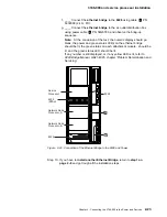
2. Verifying the Ethernet Bridge and the Attachment Modules
Notice the icon in the upper left-hand corner on the front. (See the
matching symbol in the figures below.) Verify that the token-ring module
is installed in the upper slot and the Ethernet in the lower slot of the
ethernet bridge, refer to Figure 2-11 on page 2-10.
Verify the switch setting of the modules:
For the token-ring module, switches 1 and 2 must be ON and 3 to 8
OFF.
For the Ethernet module, switch 1 must be ON and 2 to 8 OFF.
Note: Switch 7 can be set to ON if the customer will use a 10 Base
T Ethernet cable (refer to the worksheet “Parameter worksheet for
Ethernet Bridge” on page A-1).
Single Port
Token-Ring
Token-Ring
Icon
Green Status
LED
D-Shell
Connection
Yellow Status LED
Activity LED
Screw
Activity
Icon
UTP Connection
Figure
2-9. Single-Port Token-Ring Attachment Module
Ethernet
Ethernet
Icon
Green Status
LED
AUI
Connection
10BASE-T Link OK
LED and Icon
Yellow Status LED
10BASE-T Connection
Activity LED and Icon
Figure
2-10. Ethernet Attachment Module
Meaning of the attachement module indicators.
Port Status Indicators Each attachment module has a pair of status
LEDs for each port. The green status LED, when lit, indicates
that the internal tests for the port have been successfully com-
pleted; the yellow status LED, when lit, indicates a detected
internal fault.
LAN Activity Indicators Each attachment module indicates outbound
activity for each port. The green activity LED indicates that
the ethernet bridge is successfully connected to the respective
LAN and that traffic is being forwarded by the ethernet bridge
from that network.
Go to step 3 on page 2-10
Chapter 2. Connecting the 3746-900 to the Power and Devices
2-9
Содержание 3746-900
Страница 1: ...3746 Nways Multiprotocol Controller Model 900 IBM Installation Guide SY33 2114 03...
Страница 2: ......
Страница 3: ...3746 Nways Multiprotocol Controller Model 900 IBM Installation Guide SY33 2114 03...
Страница 14: ...xii 3746 900 Installation Guide...
Страница 17: ...Notices xv...
Страница 20: ...7 Power ON indicator 8 Emergency power OFF xviii 3746 900 Installation Guide...
Страница 24: ...xxii 3746 900 Installation Guide...
Страница 26: ...xxiv 3746 900 Installation Guide...
Страница 40: ...3746 900 preparing for installation 1 14 3746 900 Installation Guide...
Страница 102: ...3746 900 Test Procedure 3 14 3746 900 Installation Guide...
Страница 146: ...Cabling the 3746 900 to the 3745 X1A 4 44 3746 900 Installation Guide...
Страница 168: ...3745 Test Procedures 7 6 3746 900 Installation Guide...
Страница 198: ...3746 900 Ground Bracket Installation 9 6 3746 900 Installation Guide...
Страница 204: ...3746 900 Attached to a 3745 17A Ground Bracket Installation 10 6 3746 900 Installation Guide...
Страница 205: ...Machine Ready for Customer Chapter 11 Making the Machine Ready for the Customer Copyright IBM Corp 1996 1997 11 1...
Страница 210: ...Machine Ready for Customer 11 6 3746 900 Installation Guide...
Страница 218: ...Removal the 3746 900 Attached to a 3745 17A 13 4 3746 900 Installation Guide...
Страница 220: ...A 2 3746 900 Installation Guide...
Страница 250: ...E 14 3746 900 Installation Guide...
Страница 268: ...X 18 3746 900 Installation Guide...
Страница 272: ......
Страница 275: ......
Страница 276: ...IBM Part Number 29H4858 Printed in Denmark by IBM Danmark A S 29H4858 SY33 2114 3...