


1-1
INSTALLATION
HC SERIES BOILERS
HC 13-50, HC 23-84, HC 29-106, HC 33-124, HC 20-125, HC 33-160
INSTALLATION
1.0
GENERAL
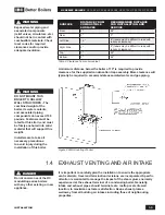
HC Series gas-fired modulating boilers are low pressure, fully condensing units
having variable input ranges
(see specification chart - inside, front cover).
The
boilers are approved as “Category IV” vented appliances using Direct Vent
(sealed combustion).
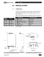
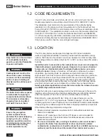
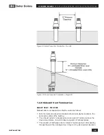
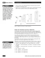
Figure 1 shows outer case dimensions and piping and electrical holes. Use this
diagram to find a suitable location for the boiler.
See also Section 1.3 Location.
DESCRIPTION
HC SERIES BOILERS
A
Exhaust Outlet
3" Schedule 40
B
Combustion Air
3" Schedule 40
E
Heating Water Inlet (Return)
1" Male NPT
F
Heating Water Outlet (Supply)
1" Male NPT
G
Gas Inlet
1/2" Male NPT
H
Condensate Outlet
3/4" Hose
I
Knock-out (3)
1/2"
Table 1: Connections
1.1
Figure 1a: Dimensions / Connections for HC Series
Figure 1b: Dimensions / Connections for HC Series
MODEL
NUMBER
HEIGHT
HC 13-50
26.6" [676]
HC 23-84
26.6" [676]
HC 29-106
29.0" [736]
HC 33-124
31.3" [796]
HC 20-125
31.3" [796]
HC 33-160
31.3" [796]
Содержание HC 33-124
Страница 76: ...SERVICE RECORD DATE LICENSED CONTRACTOR DESCRIPTION OF WORK DONE...
Страница 77: ...NOTES...


