INSTALLATION AND OPERATION INSTRUCTIONS
1-28
HC SERIES BOILERS
HC 13-50, HC 23-84, HC 29-106, HC 33-124, HC 20-125, HC 33-160
ELECTRICAL CONNECTIONS
All Electrical wiring to the boiler (including grounding) must conform to local
electrical codes and/or National Electrical Code, ANS/NFPA No. 70 – latest
edition, or The Canadian Electrical Code, C22.1 - Part 1.
If an external electrical source is utilized, the boiler, when installed, must be
electrically bonded to ground in accordance with the requirements of the authority
having jurisdiction or, in the absence of such requirements, with the
National
Electrical Code, ANSI/NFPA 70, and/or the Canadian Electrical Code Part I, CSA
C22.1, Electrical Code.
1.8.1 120VAC Line Voltage Hook-up
Line-voltage wiring is done within the field-wiring box.
(Refer to Section
6.2.Wiring Diagram on page 6-4).
Connect the boiler to the grid power using a
separate, fused circuit and on/off switch within sight of the boiler. Use 14-gauge
wire in BX cable or conduit properly anchored to the boiler case for mains supply
and pump circuits.
The boiler is equipped with 3 x 1/2" electrical knock-outs located behind the
power supply terminal strip.
Connect the 120 VAC /15 amp power supply to the AC in connections located
to the right side of the controller. To access the terminal strip, remove the boiler
cover and slide open the controller drawer. Ensure 120 VAC polarity is correct
and that the boiler is properly grounded.
The HC Series boilers include a factory installed and pre-wired pump. The pump
is intended to supply adequate flow for the boiler’s primary heating circuit only.
The system heating pump will need to be switched through a separate relay or
control box.
A second set of contacts is available to connect a DHW pump. This pump will
allow the connection of an indirect fired storage water heater to heating circuit
to take full advantage of the boilers heating capacity. The maximum amperage
rating of the connected pump is 1.0 amps. If the connected pump has a rating
higher than 1.0 amps, an external isolation relay is required to protect the boilers
controller.
A field supplied, external safety device can be connected to the boiler by
connecting the safety device in series with the boilers 120 VAC power supply.
Ensure the external safety device is rated to accept 120 VAC and the total
load connected to the boiler. For an interlock designed for the sole purpose of
protecting the heating circuit of the boiler, the Auxiliary Safety interlocks can be
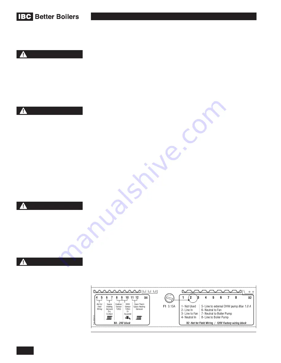
wired in series with the Call for heat (X4.6 and X4.7). Do not apply power to the
X4 terminal strip. The Auxiliary Safety interlocks must be a Dry Contact.
1.8
NOTE
The IBC control only
recognizes a true dry contact
closure as a call for heat.
Thermostats and other devices
that use a “Triac” output
cannot be used as a call for
heat without the installation of
an intervening relay with dry
contacts to connect to the IBC
terminal strip.
NOTE
The IBC boiler (like any
modern appliance that
contains electronic
equipment), must have a
“clean” power supply, and is
susceptible to power surges
and spikes, lightning strikes
and other forms of severe
electrical “noise”. Power
conditioning equipment
(surge protectors, APC or
UPS devices) may be required
in areas where power quality
is suspect.
WARNING
Do not apply power to any
connection point on the
controllers terminal strips. A
potentially hazardous situation
could occur which must be
avoided to prevent possible
serious injury or death.
Figure: 32: X4 Terminal Strip for connection of the DHW Aquastat (optional), Thermostat
or end switch’s (mandatory), Outdoor Sensor (optional)
NOTE
Some features of the control
are not available with the HC
Series boilers. The Direct
Domestic Hot Water functions
are not available however the
Indirect Domestic Hot Water
functions are available.
Содержание HC 33-124
Страница 76: ...SERVICE RECORD DATE LICENSED CONTRACTOR DESCRIPTION OF WORK DONE...
Страница 77: ...NOTES...


