INSTALLATION AND OPERATION INSTRUCTIONS
3-4
HC SERIES BOILERS
HC 13-50, HC 23-84, HC 29-106, HC 33-124, HC 20-125, HC 33-160
FUEL CONVERSION
The HC Series modulating boiler is factory fire-tested to operate with natural gas.
The rating plate will be marked to indicate which fuel the particular boiler has
been set up with. Firing a boiler with a fuel other than what is listed on the rating
plate is prohibited unless the following conversion procedure is completed by a
qualified technician.
Refer to the preceeding section 3.3 - COMMISSIONING. The Low Fire (Zero
Offset) valve adjustment cap on the gas valve has been factory set.
This cap
must not be tampered with. The Zero-offset screw is not to be adjusted in
the field.
Fuel conversion requires hardware adjustments (Orifice Replacement) as well as
measurement and possible tuning of the gas :air mixture. Detailed instructions
including parts and labeling are found in Fuel Conversion kits:
Refer to Table 9
for the correct kit number.
CO
2
VALUE (%) AT HIGH FIRE WITH THE FRONT COVER OPEN
NATURAL GAS
PROPANE
Max. CO
2
value
10.1%
11.5%
Min. CO
2
value
9.1%
9.8%
CO
2
VALUE (%) AT LOW FIRE WITH THE FRONT COVER OPEN
Max. CO
2
value
= value at Max
= value at Max – 0.3%
Min. CO
2
value
9.1%
9.5%
Table 11: CO
2
Values and High and Low Fire
The following procedure must be carried out by a qualified technician.
1.
Ensure the fuel conversion instructions supplied with the fuel conversion kit
are read, understood and followed carefully.
2.
Ensure that the gas supply is turned off at the gas control valve.
3.
Disconnect the gas valve harness plug from the gas valve.
4.
Select the correct Fuel Conversion Kit for your boiler from Table 9.
5.
Disconnect the nut at the gas valve outlet (top of the gas valve) and remove
the orifice and O-ring.
6.
Insert the correct orifice into the O-ring and re-install into the nut at the gas
valve outlet (top of the gas valve) and tighten the nut.
7.
Restore gas supply by opening the gas control valve, and using an approved
leak detection solution, soap test all joints.
8.
Place the conversion labels associated with the new fuel onto the boiler at
the positions indicated on the applicable conversion kit instruction sheet.
9.
Carefully follow the
“Prior to Start-Up” – Section 3.2 and “Commissioning” –
Section 3.3 procedures on the preceeding pages 3-2 and 3-3.
3.5.1 Gaining access to combustion chamber, burner
removal instructions
DIS-ASSEMBLY
1.
Turn off the main power switch to the boiler.
2.
Turn off the gas supply valve to the boiler.
3.4
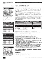
DANGER
Operating any IBC boiler
using a fuel other than the
fuel listed on its rating plate is
prohibited. If the information
in this section related to
conversion to alternate
fuels is not followed exactly,
a dangerous situation can
result, leading to fire or
explosion, which may cause
property damage, personal
injury, or loss of life.
PROPANE ORIFICE CHART
MODEL
NUMBER
ORIFICE
SIZE
HC 13-50
330
HC 23-84
505
HC 29-106
505
HC 33-124
580
HC 20-125
460
HC 33-160
580
NATURAL GAS ORIFICE
CHART
MODEL
NUMBER
ORIFICE
SIZE
HC 13-50
480
HC 23-84
650
HC 29-106
650
HC 33-124
725
HC 20-125
550
HC 33-160
725
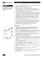
WARNING
When converting a Natural
Gas boiler to Propane, the
Back Flow Valve (located
above the outlet of the fan)
must be removed. Failure to
remove the Back Flow Valve
when using Propane fuel may
result in serious injury or
death.
Содержание HC 33-124
Страница 76: ...SERVICE RECORD DATE LICENSED CONTRACTOR DESCRIPTION OF WORK DONE...
Страница 77: ...NOTES...


