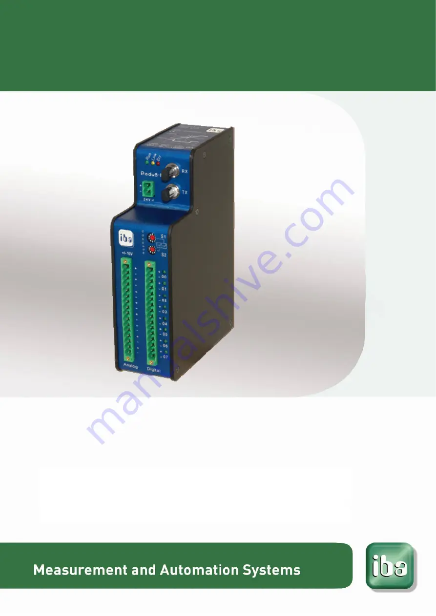
Parallel A/D Converter Unit for Fast Measurement
ibaPADU-8-M
Manual
Issue 1.9
Страница 1: ...Parallel A D Converter Unit for Fast Measurement ibaPADU 8 M Manual Issue 1 9 ...
Страница 2: ...e full compliance is not guaranteed However the information in this publication is updated regularly Required corrections are contained in the following regulations or can be downloaded on the Internet The current version is available for download on our web site http www iba ag com Protection note Windows is a label and registered trademark of the Microsoft Corporation Other product and company n...
Страница 3: ... Supply Connection X14 12 7 2 2 Fiber optic Ports RX X11 and TX X10 12 7 2 3 Setting the Device Address with S1 and S2 Decade Switches 12 7 2 4 Terminal Blocks Pin Connections X14 X1 X5 13 7 2 5 Run Link and Error LED Indicators L1 L3 13 7 2 6 Binary LED Indicators L4 L11 14 7 2 7 Service Interface X12 14 7 2 8 Shield Connector for Physical Earth X29 14 8 System integration 15 8 1 Process Monitori...
Страница 4: ...24 10 1 5 Output Resources for ibaFOB M FOB M Out 25 10 1 6 Control of ibaPADU 8 M in ibaLogic application program 26 10 1 7 Data Buffer Size 27 10 2 Configuring with ibaPDA 28 10 2 1 Configuring ibaPADU 8 M 28 10 2 2 Configuring Triggers 32 10 2 3 Configuring the Data Store 35 10 2 4 Configuring the Signal View 36 11 Technical data 37 11 1 Dimensional Drawing 38 12 Support and contact 39 ...
Страница 5: ...he is capable of assessing safety and recognizing possible consequences and risks on the basis of his her spe cialist training knowledge and experience and knowledge of the standard regulations 1 2 Notations The following designations are used in this manual Action Notations Menu command Menu Logic diagram Call of menu command Step 1 Step 2 Step 3 Step x Example Select menu Logic diagram Add New l...
Страница 6: ...ol function The non observance of this safety information may result in a potential risk of death or severe injury The non observance of this safety information may result in a potential risk of injury or material damage Note A note specifies special requirements or actions to be observed Important note Note if some special features must be observed for example exceptions from the rule Tip Tip or ...
Страница 7: ...f 96 devices can be addressed via an ibaFOB 4i 4o combination or an ibaFOB io card interface This provides a maximum of 4x96x8 3072 analog and digital measurement channels Another possible application is the simultaneous monitoring of up to 128 analog and 128 binary channels with up to 25 000 samples s This operational mode is supported by PCI cards in combination with the iba Online Data Acquisit...
Страница 8: ...ng and analysis Applications of ibaSoftware products ibaPDA ibaLogic etc The device may not be operated in mains supply circuits 4 2 Special advices Important note Do not open the device There are no serviceable parts inside the device Opening the device will void the warranty Note Cleaning To clean the device use a dry or slightly moistened cloth A note specifies special re quirements or actions ...
Страница 9: ...iber optic boards ibaFOB io S or ibaFOB 4i S ibaFOB 4o ibaFOB io D or ibaFOB io Dexp ibaFOB 2io D or ibaFOB 2io Dexp ibaFOB 4i D or ibaFOB 4i Dexp and ibaFOB 4o ibaFOB io ExpressCard for notebook 5 2 Software Online measurement monitoring software ibaScope V 3 0 01 or higher ibaLogic SoftPLC Version 3 60 or higher ibaPDA V6 Version 6 15 0 or higher ibaChatter available from iba America LLC www iba...
Страница 10: ...r supply to the termination shown on the de vice Ensure that the polarity is correct prior to applying power Finally connect fi ber optic cable to the TX RX ports as shown on the device so that the fiber optic ring is completed 6 2 Dismounting 1 Disconnect all external connections from the device 2 Grasp the device with one hand firmly on the top side With your free hand grasp the bottom of the de...
Страница 11: ...ption of configu ration requests as well as multiplexing of up to 96 devices Programmable sampling rate period between 40 µs 25 kHz and 2 ms 500 Hz in steps of 50 nanoseconds 8 analog inputs with 10 V 14 bit ADC galvanic isolation 8 binary inputs with galvanic isolation and 8 status outputs via LED Maximum device communication speed of 200 k samples per second RJ11 socket ibaCom PCMCIA interface c...
Страница 12: ...ted in a ring structure with other ibaPADU 8 M devices and the ibaFOB card links Connect the TX port of the ibaFOB card to the RX port of the first ibaPADU 8 M device in the ring Then connect the TX port of this ibaPADU 8 M device to the RX port of the next ibaPADU 8 M device in the ring Continue until all of up to 96 ibaPADU 8 M devices are interconnected Fi nally connect the TX port of the final...
Страница 13: ...channel 4 BE04 10 channel 4 BE04 11 channel 5 BE05 12 channel 5 BE05 13 channel 6 BE06 14 channel 6 BE06 15 channel 7 BE07 16 channel 7 BE07 7 2 5 Run Link and Error LED Indicators L1 L3 LED Status Indication Run green Blinking Off power is on and device is healthy no power Link yellow Off On Blinking No incoming data stream PC is inactive or the previous device in the chain is defective data is b...
Страница 14: ... to load new firmware for the device New firmware is loaded via a V 24 interface Please contact iba regarding loading new firmware Under normal service conditions the V 24 cable must not be connected Service Interface Pinout Diagram 7 2 8 Shield Connector for Physical Earth X29 Proper connection of cable shielding to the device should be ensured The shield con nector found on the underside of the ...
Страница 15: ...d in each fiber optic link must have unique ad dresses The TX port on an individual ibaFOB interface must be connected to the RX port on the first ibaPADU 8 M in the fiber optic ring Installed de vices may be interconnected in any order consecutive addresses are not required provided that all devices have unique address set tings The TX port on the last device in the chain must be connected to the...
Страница 16: ...iplex operation of the device network is not required If an ibaPADU 8 M is connected with a fiber optic link of an iba FOB card no other ibaPADU type can be connected to the same link But it is allowed to use other devices on the other links since the fiber optic links on one card can work in different modes It is possible to couple other process signals using other input devices available from ib...
Страница 17: ...nals shall be captured can be automatically done in iba Logic or manually in ibaScope or ibaPDA If an ibaPADU 8 M is connected with a fiber optic link of an iba FOB card no other ibaPADU type can be connected to the same link But it is allowed to use other devices on the other links since the fiber optic links on one card can work in different modes For example ibaPADU 8 devices can be used to mon...
Страница 18: ...ogram mable setting are to be made for this The response on a parameter request is ftp 0 Hz no filter 9 4 Input Impedance The input impedance changes with frequency Standard values for 6 dB low pass RiON 100 kOhm 100 Hz 10 kOhm 5 kHz RiOFF 50 kOhm Note At corner frequencies 1000 Hz reflected frequencies above 50x the corner frequency are possible Example 1 fc 100 Hz reflected frequency band starts...
Страница 19: ...f the device with ibaScope please refer to the ibaScope manual 10 1 Working with ibaLogic V3 With ibaLogic you may analyse 25 kHz signals By using additional slow process variables you may define monitoring ranges In order to conceive and analyze the be haviour of dynamic processes which are much faster 40 s than the usual time base of ibaLogic 1 ms the data type ARRAY is used by ibaLogic In the f...
Страница 20: ...acquisition with the major part of iba de vices such as ibaPADU 8 16 32 ibaLink SM 64 io ibaLink SM 128V i 2o ibaNet750 BM etc The fastest sample rate is 1 kHz 1 ms You may use ibaPDA ibaLogic or ibaScope as software application When using ibaLogic only an asynchro nous mode is possible i e ibaLogic can not be synchronized by ibaPADU 8 M The FOB M mode is used for fast data acquisition with sample...
Страница 21: ...ink Settings Instead of the Apply button you will find the button Save configuration which in fact has the same function There is a second button Configuration FOB M in the dialog System Settings FOB IO FOB M which opens the dialog for the preset of several parameters for FOB M mode operation You may provide presets for the listed parameters but usually the parameters are pro vided during operatio...
Страница 22: ...r the card address of this type and the LEDs showing the status of every link The physical connection is ok if the green LED is flashing and the yellow LED is on Telegrams are received by ibaPADU 8 M and the communication in output direction from ibaFOB 4o to the ibaPADU 8 M is working too On the next lower level branch Processor you will find much information about the ibaPADU 8 M or ibaPADU 8 M ...
Страница 23: ...y call the PADU setup dialog window by clicking on the button Setup Padu M Other documentation For a more detailed description of the diagnostic functions and parameters please re fer to the ibaDiag manual which can be downloaded from our website Finally there is another level in the tree with more information the module level In this view you may already see measured values running By the way thi...
Страница 24: ...B for channels 1 8 These parameters Gainx are always 0 I no gain Actual corner frequency of low pass filter for channels 1 8 These parameters Frequencyx are always 0 I no lowpass filter Actual reset status Actual command being processed Measured values of analog channels 1 8 signed integers Measured values of binary channels 1 8 Status of data buffer true if number of values buffer size Quantity o...
Страница 25: ... stream to ibaLogic Please note further that the change of parameters may affect the processing of other in and output resources due to a halt of the drivers lack of some cycles Thus ibaLogic is to be used preferably in continuous operation with few ibaPADU 8 M devices which are constantly used e g applications for test stands turbines compres sors Number of ibaPADU 8 M device to be activated Desi...
Страница 26: ...o the device over the FOB M output resources For the supply of the parameters iba developed a sample function block FOBM_Control which is available from iba on request The use of this function block is described by means of a sample application layout The inputs Run Apply and F_Reset are set by the application and control the process ing the takeover of new parameters and the resetting The applica...
Страница 27: ...lues per measuring channel Theoretical approach to the relation between continuous data streaming and ibaLogic task cycle ibaPADU 8 M sample time e g 40 µs Quantity of data to be read e g 2050 values Data reading interval in ibaLogic e g 25 ms 1 25 ms x 2050 82 000 values sec channel Data read rate DRR 1 40 µs 25 000 values sec channel Data generation rate DGR Note The data read rate must be at le...
Страница 28: ...8 M to the interrupt mode Master internal and set the option In use 2 Create the device module by one of the following actions Press the icon New configuration When the device is connected correctly the autodetect feature will find the iba PADU 8 M and place module Padu 8 M on the connected FOB link Alternatively right click the link of the FOB D or FOB S card to which the ibaPADU 8 M is con necte...
Страница 29: ...Padu 8 M from the submenu or click to the blue text link Click to add module and select the Padu 8 M inter face from the displayed list Result When the device is connected correctly with two bidirectional fibre optic links the mod ule is defined on the connected link You see the communication status OK in the Info tab of the connected links ...
Страница 30: ...OB M Link timebase see below FOB M Link timebase Set the time to a value between 40 µs and 2000 µs Note The Link timebase is valid for all other links that work in M mode The module timebase see above must be equal or an integer multiple of this link timebase Also the general acquisition timebase of ibaPDA configured in the General branch of the I O manager tree must be an integer multiple of the ...
Страница 31: ... button at the end of the name field You can also display other signal properties in the grid with a right mouse click on the headline of the grid In the same way you can parameterize the digital signals 5 To finish the configuration press OK or Apply The acquisition will start if all configured devices are connected correctly ...
Страница 32: ...gger builder dialog to create the expressions for the triggers The trigger builder is based on the ibaScope trigger editor Open the trigger builder by clicking on the expression builder icon of the digital sig nal Define the trigger events In the trigger properties you can set the name of the trigger and the comment The expression of a trigger consists of one or more parts Each part is an expressi...
Страница 33: ...ibaPADU 8 M Manual Issue 1 9 33 The custom tab contains the regular expression builder Finish the definition of one trigger event with OK Define further trigger events in the same way ...
Страница 34: ...triggers fires then the trigger pool fires The trigger can fire on a rising edge of the trigger signals or it can fire each sample the trigger signal is 1 If you want to use a trigger pool as a trigger then you have to set this option on the trigger mode form for start trigger Use the checkboxes to select which trigger signals belong to the trigger pool The selected trigger signals are marked gree...
Страница 35: ...ed as follows 1 Activate and name the data store 2 Define the Start Stop Trigger Either as a single trigger event or one or more events from the trigger pool see above 3 Define the signals to store 4 Define the data file properties File name location directory organization etc 5 To finish the configuration press the button OK at the right bottom edge of the box The data storage will be activated i...
Страница 36: ...configuration you are in the ibaPDA client main view Mainly ibaPDA has three view types The trend graph the Scope view and the FFT view Click to the icons to create the views in the signal monitor and place the dockable window in the monitor area Drag and drop the signals from the signal tree and into the signal views ...
Страница 37: ...x 400 mA IOFF ON approx 1A Sampling rate programmable up to 25 kHz 8 channels simultaneously FO cable Coupling 62 5 125 µm ST Lean Max length of FO between devices 2000 m 6560 ft Dimensions WxHxD mm inch 54 x 194 x 155 2 13 x 7 64 x 6 10 Weight incl packaging and docu mentation 1050 g 37 oz Analog inputs Number 8 Each channel has its own ADC Resolution 14 Bit Input level type RiON RiOFF 10 V 100 k...
Страница 38: ...Manual ibaPADU 8 M 38 Issue 1 9 11 1 Dimensional Drawing Dimensions given in mm ...
Страница 39: ...quire support specify the serial number iba S N of the product Contact Headquarters iba AG Koenigswarterstr 44 90762 Fuerth Germany Phone 49 911 97282 0 Fax 49 911 97282 33 Email iba iba ag com Contact Mr Harald Opel Regional and Worldwide For contact data of your regional iba office or representative please refer to our web site www iba ag com ...