


Dimensions by Stroke
Stroke
10
20
30
40
50
L
(Note 1)
Without brake
97
107
117
127
137
With brake
122
132
142
152
162
B
28
38
48
58
68
C
10
20
30
40
50
F
0
10
20
30
40
H
2
4
4
4
4
J
0
10
20
30
40
(Note 1) When selecting cable exit direction (option), 1 is subtracted from the dimensions.
Mass by Stroke
Stroke
10
20
30
40
50
Mass
(kg)
Without brake
0.14
0.17
0.19
0.21
0.23
With brake
0.16
0.19
0.21
0.23
0.25
Applicable Controllers
(Note) EC Series products are equipped with a built-in controller. Please refer to P. 25 for details on built-in controllers.
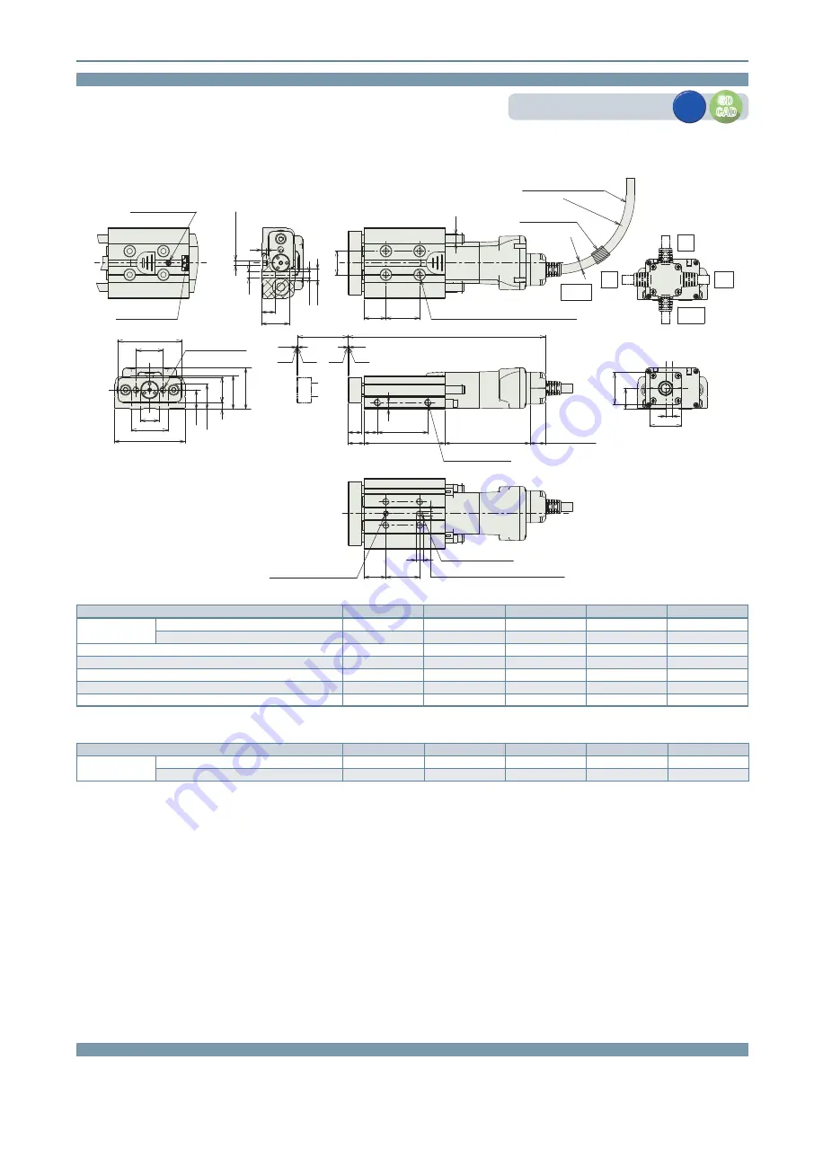
Dimensions
(Note) When returning to the home position, the rod will move to the M.E. Be careful of interference with surrounding objects.
(Note) Fix the cable so that its base does not move.
The cable can be separated and replaced. (Connected to the connector in the cable box)
The cable exit direction (option) can be changed by changing the cable box direction.
ST: Stroke
M.E: Mechanical end
S.E: Stroke end
ST
0.5
0.5
50.5 (w/o brake)
75.5 (with brake)
9 (cable rear)
8 (cable side)
9.5
L
8
B
8
C
4
2-M4 depth 8
(same on opposite side)
M.E.
Home
S.E.
M.E.
13
F
H-ø3.3 through, ø6.5 deep counterbored, depth 3.5
M4 depth 8 from opposite side
14
ø5.2
R41.6
(movable
, allowable bending r
adius)
ø5
Actuator cable
(robot cable) length 1 ~ 10m
Cable must be fixed
Standard
Back
ø3 H7 reamed, depth 3
(from the body seating surface)
13
J
(ø3 hole - oblong hole)
4
Depth 3 (from the body seating surface)
Oblong hole (not in 10ST)
24.5
M4 through
(screw depth 8 or less)
15
16
19
4
19
12.5
8
23
38
42
4
11.5
14.75
20
8
16.5
M4
ø3.3
ø6.5
ø3 H7 reamed
3
CJR
Right
CJT
Top
CJB
Bottom
CJL
Left
Cable exit direction (option)
Screw grease port ø3.3
(slide coupling cover)
Coupling flange
for manual operation
3
+0.010
0
CAD drawings can be downloaded from our website.
www.elecylinder.de
3D
CAD
3D
CAD
2D
CAD
2D
CAD
EC
EleCylinder
15
EC-GDB3