EZLOGIC CONTROL CONNECTIONS
Each zone controller has a built-in cable to provide a zone drive/no drive output to
the motor control board operating the zone. This cable is terminated with a female
Pico-style sealed snap-lock connector. Connection is made by pushing the cable
connector onto the corresponding male connector of the motor control board until
it snaps in place.
Please note that this output is only to be used to operate the zone mechanism of
the conveyor. It is not to be used as an output signal to other control devices. If a
control output is needed, an optional auxiliary I/O module should be used. Please
refer to the EzLogic® GEN3 Component Manual for more information.
AUXILIARY CONNECTIONS
Every EzLogic® zone controller is equipped with an auxiliary port to accept a zone
stop signal, a slug input signal, or a zone wake-up signal by simply connecting
an auxiliary input cable to the auxiliary port of the controller and then wiring the
two wires of the cable to any “dry contact” type switching device, such as a toggle
switch or relay. No other components are required. The default setting is for a
zone stop signal. To use the signal for slug input or zone wake-up, program the
zone controller as detailed in the EzLogic® GEN3 Component Manual.
NOTE:
Do not apply a voltage to these wires, or wire more than one controller to
any one contact.
SLUG MODE CONNECTIONS
The EzLogic® accumulation system provides two modes of accumulation which
are user-selectable: Singulation mode and Slug mode. (For descriptions of the
sequence of operation for each mode, refer to the “Sequence of Operation” section
on pages 5.) The desired mode of operation may be programmed into the zone
controllers at installation (refer to the EzLogic® GEN3 Component Manual for
details). If the user wishes to be able to alternate between singulation mode and
slug mode “on-the-fly,” an optional Auxiliary Input Cable (Hytrol P/N 032.563) may
be used. The default mode is singulation mode. If the user desires to operate the
conveyor in slug mode, or if the user wishes to be able to alternate between the
two modes as needed, the following procedures should be used.
SLUG MODE ONLY
Program the zone controllers to operate in “slug mode only” as detailed in the
EzLogic® GEN3 Component Manual.
SELECTABLE SINGULATION/SLUG
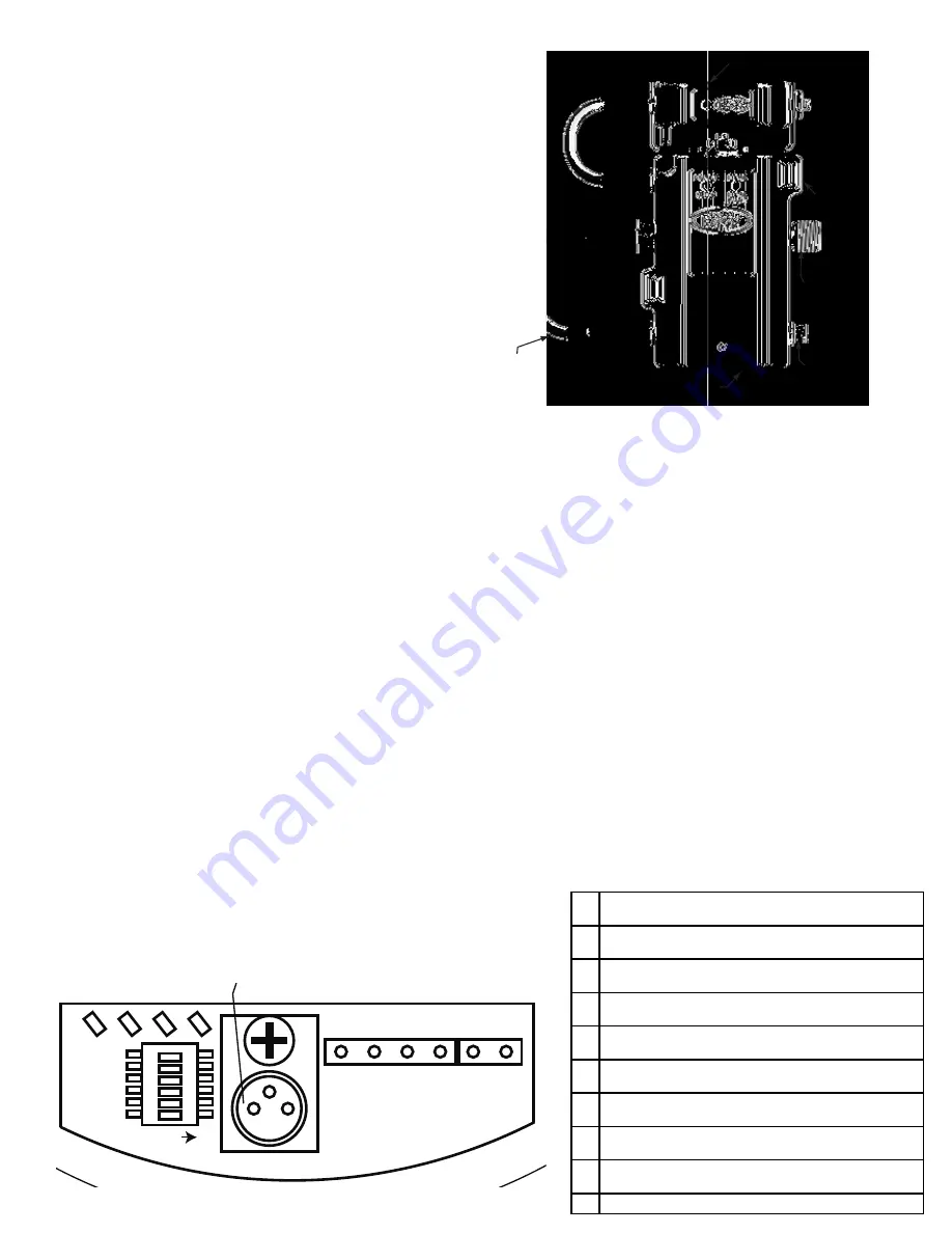
1. Install an auxiliary input cable (Hytrol P/N 032.563) on any zone controller of the
conveyor. The cable attaches to the auxiliary port on the controller. (see Figure
7A).
2. Program the zone controller to accept a slug signal. (Refer to the EzLogic®
GEN3 Component Manual for details.)
3. Connect the two wires of the Auxiliary Input Cable to any “dry contact” type
switching device, such as a toggle switch or relay.
4. With the switch contacts open, the conveyor will be in singulation mode. When
the switch is closed, the conveyor is in slug mode.
NOTE: Do not apply a voltage to these wires, or wire more than one controller
to any one contact.
• Motor Control Board Connections
+24VDC Input, DC (-) Terminals
These terminals provide power to the control board and motor. The two pin
connector from the wiring harness supplies power to this location.
EZLogic® Controller Connector
This connector accepts a drive/no drive signal from an EzLogic® zone controller
(when used). The connector is a male 8mm push-type connector that mates with
the female connector of the EzLogic® zone controller. When the control board
receives a “run” signal from the EzLogic® zone controller, it turns on the E24™
motor.
Motor Run Terminal
This terminal is used to provide a “run” signal to the motor control board when
EzLogic® is not being used, such as on the 190-E24 conveyor. The type of signal
used PNP type. This connection is OR’ed with the Ez-Logic® input. When either is
active, or when both are active, the motor will run.
Motor Direction Terminal
This terminal is used to provide a “reverse” signal to the motor control board. The
type of signal used is a PNP type. The actual definition of “forward” and “reverse”
is determined by the position of the motor rotation selector switch (switch 1). When
this input is active and either the PNP Run input or the Ez-Logic® input is also
active, the motor will run in the opposite direction from the setting on switch 1.
Analog Speed Input Terminal
This terminal may be used to override the speed set by switches 3, 4, 5 and 6.
If the input is below 0.5 VDC, the speed defaults to that set by the switches.
•
If the input is 9.0 VDC or higher, the speed will be the maximum speed.
•
If in the range of 1.0 to 9.0 VDC, the speed will be proportional to the input.
•
If the input is in the 0.5 to 1.0 VDC range, the speed will be the minimum
•
speed.
Motor Running Output Terminal
This terminal is used to provide a “motor running” signal from the motor control
board. The output is a PNP type output and is active as long as the motor
controlled by the control board is running. This output is not used on standard
configurations of the E24™ family of conveyors, but may be used in special
applications, such as when two E24™ motors are required in one conveyor zone
to handle heavier loads.
Power Indicator LED (Green)
This LED will be illuminated at all times if input power is connected to the controller
with the proper polarity and the fuse is not blown.
Current Limiting Indicator LED (Amber)
Four Flashes in 4 seconds:
•
Components have overheated and the circuit is
limiting the power to the motor to about half (50%) of normal. This problem
corrects itself when the motor has adequately cooled. Check for mechanical
obstructions.
Constantly ON:
•
Motor current is at the maximum allowed and is being
electronically limited. Check for mechanical obstructions.
Flickering:
•
If the motor starts under significant load, the current may be
limited briefly causing the LED to flicker. If the LED flickers constantly, this
is an indication that the motor is operating at its upper limit and may never
TRANSDUCER
MOUNTING BASE
AUXILIARY PORT
ZONE CONTROLLER
SOLENOID OUTPUT CABLE
CORDSET
(CONECTOR DE CABLE)
(BASE DE MONTAJE)
(SENSOR)
(CABLE DE SALIDA SELENOIDE)
(CONTROLADOR DE ZONA)
(PUERTO AUXILIAR)
FIGURE 7A
• Zone Controller for GEN3 EZLogic
®
1
2
3
4
5
6
P1
P2
P3
P4
1
2
EZLOGIC CONTROLLER CONNECTOR
(CONECTOR DEL CONTROLADOR EZLOGIC)
ON
L1
L2
L3
L4
L1 AMBER LED (CURRENT LIMITING)
IndICadOr led naranJa (IndICa COrrIente lImItada)
L2 RED LED (FAULT)
IndICadOr led rOJO (Falla)
L3 GREEN LED (POWER)
IndICadOr led Verde (pOtenCIa)
L4 RED LED (BLOWN FUSE)
IndICadOr led rOJO (FUsIble FUndIdO)
P1 MOTOR RUN INPUT
entrada de arranQUÉ del mOtOr
P2 MOTOR DIRECTION INPUT
entrada de dIreCCIOn del mOtOr
P3 ANALOG SPEED INPUT
salIda de VelOCIdad analógICa
P4 MOTOR RUNNING OUTPUT
salIda de mOtOr en marCHa
1
24 VDC INPUT
entrada de COrrIente d24V dC
2
DC (-)
COrrIente dIreCta dC (-)
FIGURE 7B
7


