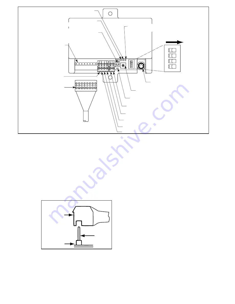
EZLOGIC® CONTROLLER CONNECTOR
(CONECTOR DEL CONTROLADOR EZLOGIC)
SPEED CONTROL POTENTIOMETER
(CONTROLADOR DE VELOCIDAD)
RED L.E.D. (BLOWN FUSE INDICATOR
)
(INDICADOR LED ROJO (INDICADOR DE FUSIBLE FUNDIDO)
DC (-)
(CORRIENTE DIRECTA DC (-)
+24V DC INPUT
(ENTRADA DE CORRIENTE D24V DC)
MOTOR RUNNING OUTPUT
(SALIDA DE MOTOR EN FUNCIONAMIENTO)
ANALOG SPEED INPUT
(SALIDA DE VELOCIDAD ANALÓGICA)
MOTOR DIRECTION
(DIRECCION DEL MOTOR)
MOTOR RUN
(ARRANQUE DEL MOTOR)
MOTOR CABLE
(CABLE DEL MOTOR)
MOTOR CONNNECTOR
(CONECTOR DEL MOTOR)
REPLACEABLE FUSE
(LITTEL FUSE 0454005 OR EQUIVALENT)
[(FUSIBLE REEMPLAZABLE (FUSIBLE LITTLE
0454005 O EQUIVALENTE)]
RED L.E.D. (FAULT)
[INDICADOR LED ROJO (FALLA)]
AMBER L.E.D. (INIDCATES CURRENT LIMITING)
[INDICADOR LED NARANJA (INDICA CORRIENTE LIMITADA)]
GREEN L.E.D.
(POWER CONNECTED)
INDICADOR LED VERDE (POTENCIA CONECTADA)
SW1
SW2
SW3
SW4
ON
(PRENDIDO)
FIGURE 14A
• The Motor Control Board
The motor control board is an integral part of the E24™ system. The control
board performs the following functions:
1. Provides power to the motor.
2. Allows the motor to be operated by an EzLogic® zone controller or other
control device.
3. Limits the current to the motor to protect the motor from damage in the case
of an overload or stall condition.
4. Provides optional dynamic braking.
5. Allows the default direction of rotation to be selected.
6. Provides speed control for the motor.
7. Provides LED’s to indicate when the board is receiving power and when
certain fault conditions occur.
The parts of the motor control board are shown in Figure 14A. Each of these
parts and their function are described below.
Plug the motor connec-
tor into the 8-pin header
(item 1) on the board,
oriented as shown in
Figure 14B: Orientation
of Motor Connector and
Plug. The notch in the
bottom of the plug fits
securely over the black
bar on the pin header.
NOTE: Incorrect as-
sembly of the motor
plug to the control
card will result in a
damaged motor and card.
+24VDC Input, DC (-) Terminals
These terminals provide power to the control board and motor. The two pin
connector from the wiring harness supplies power to this location.
Replaceable Fuse
The replaceable fuse protects the motor and control board from damage
due to electrical shorts and overloads. Replacements must be 5A slow blow
Littelfuse #0454005 or equivalent.
EZLogic® Controller Connector
This connector accepts a drive/no drive signal from an EzLogic® zone
controller (when used). The connector is a male 8mm push-type connector
that mates with the female connector of the EzLogic® zone controller. When
the control board receives a “run” signal from the EzLogic® zone controller,
it turns on the E24™ motor.
Motor Run Terminal
This terminal is used to provide a “run” signal to the motor control board
when EzLogic® is not being used, such as on the 190-E24 conveyor. The
type of signal used may be NPN type or PNP type and is determined by the
position of the input type selector switch (switch 2). For the 190-E24 conveyor
the switch is set to PNP mode. This means that each time this terminal is
connected to 24DC(+), or ground the motor will run.
Motor Direction Terminal
This terminal is used to provide a “reverse” signal to the motor control board.
The type of signal used may be NPN type or PNP type and is determined by
the position of the input type selector switch (switch 2). The actual definition
of “forward” and “reverse” is determined by the position of the motor rotation
selector switch (switch 1). This input is not used on standard configurations of
the E24™ family of conveyors, but may be used in special applications.
Analog Speed Input
This terminal is used to send an analog speed input to the motor control
boards. The signal may range from 0 to 10 VDC. As the input voltage
increases, the speed of the motor will increase in 16 increments. If the signal
is not present or drops below 1 VDC, the board reverts back to the on board
speed potentiometer. Maximum speed is acquired at or above 9 VDC.
Motor Running Output Terminal
This terminal is used to provide a “motor running” signal from the motor control
board. The output is a PNP type output and is active as long as the motor
controlled by the control board is running. This output is not used on standard
configurations of the E24™ family of conveyors, but may be used in special
applications, such as when two E24™ motors are required in one conveyor
zone to handle heavier loads. Input and output can be set independently of
signal from EzLogic® module.
Power Indicator LED (Green)
This LED will be illuminated at all times if input power is connected to the
controller with the proper polarity.
Current Limiting Indicator LED (Amber)
This LED will be illuminated if the board is in current limiting mode. This
8-PIN MOTOR
CONNECTOR
(8-PIN MOTOR
CONNECTOR)
CABLE
CONNECTOR
PLUG
(CABLE
CONECTOR
ENCHUFE)
ITEM 1
FIGURE 14B
14


