29
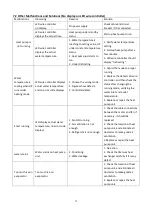
EE 26
Four-way valve
reversal failure
1.
Four-way valve reversal failure
2.
Lack of refrigerant (no detect
when T3 or T5 malfunction)
1.
Switch to Cooling mode to check the
4-way valve if it has been reversed
correctly
2.
Change a new 4-way valve
3.
Fill with gas
EE 27
EEPROM data read
malfunction
1.
Wrong EEPROM data in the
program or failed input of EEPROM
data
2.
Main board failure
1.
Re-enter correct EEPROM data
2.
Change a new main board
EE 28
The inter-chip
communication
failure on the main
control board
Main board failure
1.
Turn off electricity supply and
restart it
2.
Change a new main board
PP 01
Inlet water
temperature sensor
failure
1.
The sensor failure or short circuit
2.
The wiring of sensor is loose
1.
Re-fix the wiring of the sensors
2.
Change the sensor
PP 02
Outlet water
temperature sensor
failure
1.
The sensor failure or short circuit
2.
The wiring of sensor is loose
1.
Re-fix the wiring of the sensors
2.
Change the sensor
PP 03
Heating piping
sensor failure
1.
The sensor failure or short circuit
2.
The wiring of sensor is loose
1.
Re-fix the wiring of the sensors
2.
Change the sensor
PP 04
Gas return sensor
failure
1.
The sensor failure or short circuit
2.
The wiring of sensor is loose
1.
Re-fix the wiring of the sensors
2.
Change the sensor
PP 05
Ambient
temperature sensor
failure
1.
The sensor failure or short circuit
2.
The wiring of sensor is loose
1.
Re-fix the wiring of the sensors
2.
Change the sensor
PP 06
Exhaust piping
sensor failure
1.
The sensor failure or short circuit
2.
The wiring of sensor is loose
1.
Re-fix the wiring of the sensors
2.
Change the sensor
PP 07
Antifreeze
protection in
Winter
Ambient temperature or water inlet
temperature is too low
Normal protection
PP 08
Low ambient
temperature
protection
1.
Beyond the scope of using
environment
2.
Sensor abnormality
1.
Stop using, beyond the scope of
using
2.
Change the sensor
PP 10
Piping temperature
too high protection
under cooling mode
1.
Ambient temperature is too high
or the water temperature is too high
in cooling mode
2.
Refrigeration system is abnormal
1.
Check the scope of using
2.
Check refrigeration system
PP 11
Water temperature
(T2) too low
protection under
cooling mode
1.
Low water flow
2.
T2 temperature sensor abnormal
1.
Check water pump and waterway
system
2.
Change T2 temperature sensor
Содержание 7024515
Страница 12: ...10 2 Dimension mm Model Z7 32 Model Z11 32 Z14 32 Z16 32 ...
Страница 13: ...11 Model Z19 32 Model Z24 32 Z24T Z29 32 Z29T ...
Страница 20: ...18 5 Electrical Wiring 5 1 SWIMMING POOL HEAT PUMP WIRING DIADRAM Z7 32 Z11 32 Z14 32 Z16 32 Z19 32 ...
Страница 21: ...19 5 2 SWIMMING POOL HEAT PUMP WIRING DIADRAM Z24 32 ...
Страница 22: ...20 5 3 SWIMMING POOL HEAT PUMP WIRING DIADRAM Z29 32 ...
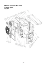
Страница 35: ...33 8 Exploded Diagram and Maintenance 8 1 Exploded Diagram Model Z7 32 ...
Страница 36: ...34 ...
Страница 38: ...36 Model Z24 32 ...
Страница 39: ...37 ...
Страница 48: ...46 2 Dimension Model Z7 32 Model Z11 32 Z14 32 Z16 32 ...
Страница 49: ...47 Model Z19 32 Model Z24 32 Z24T Z29 32 Z29T ...
Страница 57: ...55 5 2 SCHEMA DE CABLAGE DE POMPE À CHALEUR DE PISCINE Z24 32 ...
Страница 58: ...56 5 3 SCHEMA DE CABLAGE DE LA POMPE À CHALEUR DE PISCINE Z29 32 ...
Страница 72: ...70 8 Schéma eclaté et entretien 8 1 Schéma eclaté Model Z7 32 ...
Страница 73: ...71 ...
Страница 75: ...73 Model Z24 32 ...
Страница 76: ...74 ...
Страница 85: ...83 2 Afmeting Dimension Model Z7 32 Model Z11 32 Z14 32 Z16 32 ...
Страница 86: ...84 Model Z19 32 Model Z24 32 Z24T Z29 32 Z29T ...
Страница 93: ...91 5 Elektrische bedrading 5 1 ZWEMBAD WARMTEPOMP BEDRADING SCHEMA Z7 32 Z11 32 Z14 32 Z16 32 Z19 32 ...
Страница 94: ...92 5 2 ZWEMBAD WARMTEPOMP BEDRADING SCHEMA Z24 32 ...
Страница 95: ...93 5 3 ZWEMBAD WARMTEPOMP BEDRADING SCHEMA Z29 32 ...
Страница 109: ...107 8 Open geklapt diagram en onderhoud 8 1 Open geklapt diagram Model Z7 32 ...
Страница 110: ...108 ...
Страница 112: ...110 Model Z24 32 ...
Страница 113: ...111 ...
Страница 122: ...120 2 Ausmaße Model Z7 32 Model Z11 32 Z14 32 Z16 32 ...
Страница 123: ...121 Model Z19 32 Model Z24 32 Z24T Z29 32 Z29T ...
Страница 130: ...128 5 1 VERKABELUNGSDIAGRAMM DER SCHWIMMBECKEN WÄRMEPUMPE Z7 32 Z11 32 Z14 32 Z16 32 Z19 32 ...
Страница 131: ...129 5 2 VERKABELUNGSDIAGRAMM DER SCHWIMMBECKEN WÄRMEPUMPE Z24 32 ...
Страница 132: ...130 5 3 VERKABELUNGSDIAGRAMM DER SCHWIMMBECKEN WÄRMEPUMPE Z29 32 ...
Страница 146: ...144 8 Explosionszeichnung und Wartung 8 1 Explosionszeichnung Model Z7 32 ...
Страница 147: ...145 ...
Страница 149: ...147 Model Z24 32 ...
Страница 150: ...148 ...
Страница 159: ...157 2 Wymiary Model Z7 32 Model Z11 32 Z14 32 Z16 32 ...
Страница 160: ...158 Model Z19 32 Model Z24 32 Z24T Z29 32 Z29T ...
Страница 168: ...166 5 2 SCHEMAT OKABLOWANIA POMPY GRZEWCZEJ DO BASENOW KĄPIELOWYCH Z24 32 ...
Страница 169: ...167 5 3 SCHEMAT OKABLOWANIA POMPY GRZEWCZEJ DO BASENOW KĄPIELOWYCH Z29 32 ...
Страница 183: ...181 8 Schemat budowy pompy 8 1 Widok urządzenia rozebranego Model Z7 32 ...
Страница 184: ...182 ...
Страница 186: ...184 Model Z24 32 ...
Страница 187: ...185 ...
Страница 196: ...194 2 Dimension mm Model Z7 32 Model Z11 32 Z14 32 Z16 32 ...
Страница 197: ...195 Model Z19 32 Model Z24 32 Z24T Z29 32 Z29T ...
Страница 204: ...202 5 elektrisk ledningsføring 5 1 SWIMMINGPOOL VARMEPUMPE WIRING DIAGRAM Z7 32 Z11 32 Z14 32 Z16 32 Z19 32 ...
Страница 205: ...203 5 2 SWIMMINGPOOL VARMEPUMPE WIRING DIAGRAM Z24 32 ...
Страница 206: ...204 5 3 SWIMMINGPOOL VARMEPUMPE WIRING DIAGRAM Z29 32 ...
Страница 220: ...218 8 Eksploderede Diagram og vedligeholdelse 8 1 Eksploderede Diagram Model Z7 32 ...
Страница 221: ...219 ...
Страница 223: ...221 Model Z24 32 ...
Страница 224: ...222 ...
Страница 230: ...228 A0111HYIR3201 ...


