32
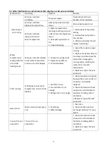
7.2 Other Malfunctions and Solutions (No display on LED wire controller)
Malfunctions
Observing
Reasons
Solution
Heat pump is
not running
LED wire controller
no display.
No power supply
Check cable and circuit
breaker if it is connected
LED wire controller.
displays the actual time.
Heat pump under standby
status
Startup heat pump to run.
LED wire controller
displays the actual
water temperature.
1. Water temperature is
reaching to setting value, HP
under constant temperature
status.
2. Heat pump just starts to
run.
3. Under defrosting.
1. Verify water temperature
setting.
2. Startup heat pump after a
few minutes.
3. LED wire controller should
display "Defrosting".
Water
temperature is
cooling when HP
runs under
heating mode
LED wire controller displays
actual water temperature
and no error code displays.
1. Choose the wrong mode.
2. Figures show defects.
3. Controller defect.
1. Adjust the mode to proper
running
2. Replace the defect LED wire
controller, and then check the
status after changing the
running mode, verifying the
water inlet and outlet
temperature.
3. Replace or repair the heat
pump unit
Short running
LED displays actual water
temperature, no error code
displays.
1. Fan NO running.
2. Air ventilation is not
enough.
3. Refrigerant is not enough.
1. Check the cable connections
between the motor and fan, if
necessary, it should be
replaced.
2. Check the location of heat
pump unit, and eliminate all
obstacles to make good air
ventilation.
3 Replace or repair the heat
pump unit.
water stains
Water stains on heat pump
unit.
1. Concreting.
2. Water leakage.
1. No action.
2. Check the titanium heat
exchanger carefully if it is any
defect.
Too much ice on
evaporator
Too much ice on
evaporator.
1. Check the location of heat
pump unit, and eliminate all
obstacles to make good air
ventilation.
2. Replace or repair the heat
pump unit.
Содержание 7024515
Страница 12: ...10 2 Dimension mm Model Z7 32 Model Z11 32 Z14 32 Z16 32 ...
Страница 13: ...11 Model Z19 32 Model Z24 32 Z24T Z29 32 Z29T ...
Страница 20: ...18 5 Electrical Wiring 5 1 SWIMMING POOL HEAT PUMP WIRING DIADRAM Z7 32 Z11 32 Z14 32 Z16 32 Z19 32 ...
Страница 21: ...19 5 2 SWIMMING POOL HEAT PUMP WIRING DIADRAM Z24 32 ...
Страница 22: ...20 5 3 SWIMMING POOL HEAT PUMP WIRING DIADRAM Z29 32 ...
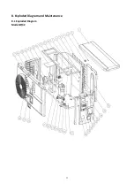
Страница 35: ...33 8 Exploded Diagram and Maintenance 8 1 Exploded Diagram Model Z7 32 ...
Страница 36: ...34 ...
Страница 38: ...36 Model Z24 32 ...
Страница 39: ...37 ...
Страница 48: ...46 2 Dimension Model Z7 32 Model Z11 32 Z14 32 Z16 32 ...
Страница 49: ...47 Model Z19 32 Model Z24 32 Z24T Z29 32 Z29T ...
Страница 57: ...55 5 2 SCHEMA DE CABLAGE DE POMPE À CHALEUR DE PISCINE Z24 32 ...
Страница 58: ...56 5 3 SCHEMA DE CABLAGE DE LA POMPE À CHALEUR DE PISCINE Z29 32 ...
Страница 72: ...70 8 Schéma eclaté et entretien 8 1 Schéma eclaté Model Z7 32 ...
Страница 73: ...71 ...
Страница 75: ...73 Model Z24 32 ...
Страница 76: ...74 ...
Страница 85: ...83 2 Afmeting Dimension Model Z7 32 Model Z11 32 Z14 32 Z16 32 ...
Страница 86: ...84 Model Z19 32 Model Z24 32 Z24T Z29 32 Z29T ...
Страница 93: ...91 5 Elektrische bedrading 5 1 ZWEMBAD WARMTEPOMP BEDRADING SCHEMA Z7 32 Z11 32 Z14 32 Z16 32 Z19 32 ...
Страница 94: ...92 5 2 ZWEMBAD WARMTEPOMP BEDRADING SCHEMA Z24 32 ...
Страница 95: ...93 5 3 ZWEMBAD WARMTEPOMP BEDRADING SCHEMA Z29 32 ...
Страница 109: ...107 8 Open geklapt diagram en onderhoud 8 1 Open geklapt diagram Model Z7 32 ...
Страница 110: ...108 ...
Страница 112: ...110 Model Z24 32 ...
Страница 113: ...111 ...
Страница 122: ...120 2 Ausmaße Model Z7 32 Model Z11 32 Z14 32 Z16 32 ...
Страница 123: ...121 Model Z19 32 Model Z24 32 Z24T Z29 32 Z29T ...
Страница 130: ...128 5 1 VERKABELUNGSDIAGRAMM DER SCHWIMMBECKEN WÄRMEPUMPE Z7 32 Z11 32 Z14 32 Z16 32 Z19 32 ...
Страница 131: ...129 5 2 VERKABELUNGSDIAGRAMM DER SCHWIMMBECKEN WÄRMEPUMPE Z24 32 ...
Страница 132: ...130 5 3 VERKABELUNGSDIAGRAMM DER SCHWIMMBECKEN WÄRMEPUMPE Z29 32 ...
Страница 146: ...144 8 Explosionszeichnung und Wartung 8 1 Explosionszeichnung Model Z7 32 ...
Страница 147: ...145 ...
Страница 149: ...147 Model Z24 32 ...
Страница 150: ...148 ...
Страница 159: ...157 2 Wymiary Model Z7 32 Model Z11 32 Z14 32 Z16 32 ...
Страница 160: ...158 Model Z19 32 Model Z24 32 Z24T Z29 32 Z29T ...
Страница 168: ...166 5 2 SCHEMAT OKABLOWANIA POMPY GRZEWCZEJ DO BASENOW KĄPIELOWYCH Z24 32 ...
Страница 169: ...167 5 3 SCHEMAT OKABLOWANIA POMPY GRZEWCZEJ DO BASENOW KĄPIELOWYCH Z29 32 ...
Страница 183: ...181 8 Schemat budowy pompy 8 1 Widok urządzenia rozebranego Model Z7 32 ...
Страница 184: ...182 ...
Страница 186: ...184 Model Z24 32 ...
Страница 187: ...185 ...
Страница 196: ...194 2 Dimension mm Model Z7 32 Model Z11 32 Z14 32 Z16 32 ...
Страница 197: ...195 Model Z19 32 Model Z24 32 Z24T Z29 32 Z29T ...
Страница 204: ...202 5 elektrisk ledningsføring 5 1 SWIMMINGPOOL VARMEPUMPE WIRING DIAGRAM Z7 32 Z11 32 Z14 32 Z16 32 Z19 32 ...
Страница 205: ...203 5 2 SWIMMINGPOOL VARMEPUMPE WIRING DIAGRAM Z24 32 ...
Страница 206: ...204 5 3 SWIMMINGPOOL VARMEPUMPE WIRING DIAGRAM Z29 32 ...
Страница 220: ...218 8 Eksploderede Diagram og vedligeholdelse 8 1 Eksploderede Diagram Model Z7 32 ...
Страница 221: ...219 ...
Страница 223: ...221 Model Z24 32 ...
Страница 224: ...222 ...
Страница 230: ...228 A0111HYIR3201 ...


