28
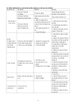
EE 15
Temperature of IPM
module is too high
1.
Output exception of IPM module
thermal circuit
2.
Motor is abnormal or damaged
3.
Fan blade is broken
1.
Change a driver board
2.
Check if the fan motor speed is too
low or fan motor damaged, change
another one
3.
Change another fan blade
EE 16
PFC module
protection
1.
Output exception of PFC module
2.
Motor is abnormal or damaged
3.
Fan blade is broken
4.
Input voltage leap, input power is
abnormal
1.
Change a driver board
2.
Check if the motor speed is too low
or fan motor damaged, change
another one
3.
Change another fan blade
4.
Check the input voltage
EE 17
DC fan motor
failure
1.
DC motor is damaged
2.
Main board is damaged
3.
The fan blade is stuck
1.
Detect DC motor, replace with a
new one
2.
Change a new main board
3.
Find out the barrier and work it out
EE 18
PFC module
thermal circuit is
abnormal
The driver board is damaged
1.
Change a new driver board
2.
Check if the fan motor speed is too
low or fan motor damaged, change
another one
EE 19
PFC module high
temperature
protection
1.
PFC module thermal circuit output
abnormal
2.
Motor is abnormal or damaged
3.
Fan blade is broken
4.
The screw in the driver board is
not tight
1.
Change a new driver board
2.
Check if the motor speed is too low
or fan motor damaged, change
another one
3.
Change another fan blade
4.
Check if the screw is loose
EE 20
The input power
failure
Power supply voltage fluctuates too
much
Check whether the voltage is stable
EE 21
Software control
exception
1.
Compressor run out of step
2.
Wrong program
3.
Impurity inside compressor causes
the unstable rotate speed
1.
Check the main board or change a
new one
2.
Enter correct program
EE 22
Current detection
circuit failure
1.
Voltage signal abnormal
2.
Driver board is damaged
1.
Check the main board or change a
new one
2.
Change a new driver board
EE 23
Compressor startup
failed
1.
Main board is damaged
2.
Compressor wiring error or poor
contact or unconnected
3.
Liquid accumulation inside
4.
Wrong phase connection for
compressor
1.
Check the main board or change a
new one
2.
Check
the
compressor
wiring
according to the circuit diagram
Check the compressor or change a
new one
EE 24
Ambient
Temperature device
failure on Driver
board
Ambient Temperature device failure
Change driver board or main board
EE 25
Compressor phase
failure
Compressors U, V, W are connected
to one phase or two phases
Check the actual wiring according to
the circuit diagram
Содержание 7024515
Страница 12: ...10 2 Dimension mm Model Z7 32 Model Z11 32 Z14 32 Z16 32 ...
Страница 13: ...11 Model Z19 32 Model Z24 32 Z24T Z29 32 Z29T ...
Страница 20: ...18 5 Electrical Wiring 5 1 SWIMMING POOL HEAT PUMP WIRING DIADRAM Z7 32 Z11 32 Z14 32 Z16 32 Z19 32 ...
Страница 21: ...19 5 2 SWIMMING POOL HEAT PUMP WIRING DIADRAM Z24 32 ...
Страница 22: ...20 5 3 SWIMMING POOL HEAT PUMP WIRING DIADRAM Z29 32 ...
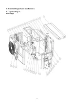
Страница 35: ...33 8 Exploded Diagram and Maintenance 8 1 Exploded Diagram Model Z7 32 ...
Страница 36: ...34 ...
Страница 38: ...36 Model Z24 32 ...
Страница 39: ...37 ...
Страница 48: ...46 2 Dimension Model Z7 32 Model Z11 32 Z14 32 Z16 32 ...
Страница 49: ...47 Model Z19 32 Model Z24 32 Z24T Z29 32 Z29T ...
Страница 57: ...55 5 2 SCHEMA DE CABLAGE DE POMPE À CHALEUR DE PISCINE Z24 32 ...
Страница 58: ...56 5 3 SCHEMA DE CABLAGE DE LA POMPE À CHALEUR DE PISCINE Z29 32 ...
Страница 72: ...70 8 Schéma eclaté et entretien 8 1 Schéma eclaté Model Z7 32 ...
Страница 73: ...71 ...
Страница 75: ...73 Model Z24 32 ...
Страница 76: ...74 ...
Страница 85: ...83 2 Afmeting Dimension Model Z7 32 Model Z11 32 Z14 32 Z16 32 ...
Страница 86: ...84 Model Z19 32 Model Z24 32 Z24T Z29 32 Z29T ...
Страница 93: ...91 5 Elektrische bedrading 5 1 ZWEMBAD WARMTEPOMP BEDRADING SCHEMA Z7 32 Z11 32 Z14 32 Z16 32 Z19 32 ...
Страница 94: ...92 5 2 ZWEMBAD WARMTEPOMP BEDRADING SCHEMA Z24 32 ...
Страница 95: ...93 5 3 ZWEMBAD WARMTEPOMP BEDRADING SCHEMA Z29 32 ...
Страница 109: ...107 8 Open geklapt diagram en onderhoud 8 1 Open geklapt diagram Model Z7 32 ...
Страница 110: ...108 ...
Страница 112: ...110 Model Z24 32 ...
Страница 113: ...111 ...
Страница 122: ...120 2 Ausmaße Model Z7 32 Model Z11 32 Z14 32 Z16 32 ...
Страница 123: ...121 Model Z19 32 Model Z24 32 Z24T Z29 32 Z29T ...
Страница 130: ...128 5 1 VERKABELUNGSDIAGRAMM DER SCHWIMMBECKEN WÄRMEPUMPE Z7 32 Z11 32 Z14 32 Z16 32 Z19 32 ...
Страница 131: ...129 5 2 VERKABELUNGSDIAGRAMM DER SCHWIMMBECKEN WÄRMEPUMPE Z24 32 ...
Страница 132: ...130 5 3 VERKABELUNGSDIAGRAMM DER SCHWIMMBECKEN WÄRMEPUMPE Z29 32 ...
Страница 146: ...144 8 Explosionszeichnung und Wartung 8 1 Explosionszeichnung Model Z7 32 ...
Страница 147: ...145 ...
Страница 149: ...147 Model Z24 32 ...
Страница 150: ...148 ...
Страница 159: ...157 2 Wymiary Model Z7 32 Model Z11 32 Z14 32 Z16 32 ...
Страница 160: ...158 Model Z19 32 Model Z24 32 Z24T Z29 32 Z29T ...
Страница 168: ...166 5 2 SCHEMAT OKABLOWANIA POMPY GRZEWCZEJ DO BASENOW KĄPIELOWYCH Z24 32 ...
Страница 169: ...167 5 3 SCHEMAT OKABLOWANIA POMPY GRZEWCZEJ DO BASENOW KĄPIELOWYCH Z29 32 ...
Страница 183: ...181 8 Schemat budowy pompy 8 1 Widok urządzenia rozebranego Model Z7 32 ...
Страница 184: ...182 ...
Страница 186: ...184 Model Z24 32 ...
Страница 187: ...185 ...
Страница 196: ...194 2 Dimension mm Model Z7 32 Model Z11 32 Z14 32 Z16 32 ...
Страница 197: ...195 Model Z19 32 Model Z24 32 Z24T Z29 32 Z29T ...
Страница 204: ...202 5 elektrisk ledningsføring 5 1 SWIMMINGPOOL VARMEPUMPE WIRING DIAGRAM Z7 32 Z11 32 Z14 32 Z16 32 Z19 32 ...
Страница 205: ...203 5 2 SWIMMINGPOOL VARMEPUMPE WIRING DIAGRAM Z24 32 ...
Страница 206: ...204 5 3 SWIMMINGPOOL VARMEPUMPE WIRING DIAGRAM Z29 32 ...
Страница 220: ...218 8 Eksploderede Diagram og vedligeholdelse 8 1 Eksploderede Diagram Model Z7 32 ...
Страница 221: ...219 ...
Страница 223: ...221 Model Z24 32 ...
Страница 224: ...222 ...
Страница 230: ...228 A0111HYIR3201 ...


