45
fi
g. 2.6
A
B
2 - S
ਠਥਤਲ਼ਸ
D
ਤਵਨਢਤਲ
Emergency Descent Control System
Emergency descent procedure for a multiple units installation (cont’d)
Safety Devices
End of structure
still
operating
normally
End of structure
using
emergency
descent
WARNING
If the
emergency descent must be interrupted
, open the manual pump relief
valve by turning the knob
counterclockwise
or lift the upper control valve lever
(“3”, in fi g. 2.2, p. 43) to release the hydraulic pressure. On an F300 unit
model used in a
linked confi guration
, this step can be performed on either side
of the mast. In a multiple units confi guration, immediately stop the descent of the
unit at the operating end of the bearing structure.
8-
Once the oil level and temperature have been verifi ed and are appropriate, lift and
remove the plastic hood on the left-hand side of the control panel (fi g. 2.5, p. 43) to
access the control valve levers and the manual pump. On an
F300 unit model used
in a linked confi guration
, perform this step on
both sides of the mast
.
9-
Under normal operating conditions, all three control valve levers are in the
UP
position.
To activate the emergency descent system, pull all three levers down, beginning with
the bottom lever (see sequence illustrated in fi g. 2.2, p. 43). On an
F300 unit model
used in a linked confi guration
, perform this step on
both sides of the mast
.
10-
Once all three levers are down, close the manual pump relief valve by turning the knob
clockwise (fi g. 2.3, p. 43). On an
F300 unit model used in a linked confi guration
,
perform this step on
both sides of the mast
.
11-
Build up hydraulic pressure by operating the pump handle back and forth
throughout
the emergency descent (fi g. 2.4, p. 43). On an
F300 unit model used in a linked
confi guration
, perform this step on
either side of the mast
. The motorized unit will
descend at a speed between 5' (1,5 m) and 10' (3 m) a minute.
12-
As the end of the bearing structure in emergency descent begins to descend, select
fi rst speed
on the control panel at the
operating end of the bearing structure
to
bring that side down
as simultaneously as possible
.
It is important to note that the inclinometer is disabled on the unit using the emergency
descent system. While the inclinometer should work at the operating end, it is
crucial
to visually monitor the descent of the structure and to make sure that the structure
remains as level as possible.
13-
If the
emergency descent must be interrupted
, immediately stop the unit at the
operating end
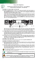
of the structure (“A”, in fi g. 2.6). On the unit at the end using the
emergency descent (“B”, in fi g. 2.6), open the manual pump relief valve by turning
the knob
counterclockwise
or by lifting the upper control valve lever (“3” in fi g. 2.2,
p. 43) to release the hydraulic pressure. On an
F300 unit model used in a linked
confi guration
, this step can be performed on
either side of the mast
.
14-
To reactivate the emergency descent, close the manual pump relief valve again (see
step 11 above). On an
F300 unit model used in a linked confi guration
, perform this
step on
the side where the relief valve was opened
(see step 14).
15-
Once the structure has been brought safely to the
nearest evacuation point
, open
the manual pump relief valve by turning the knob
counterclockwise
and raise all
three levers, starting from the top. Replace the plastic hood and secure in place. The
engine cannot be started if all or any of the levers of the control valves are down. On
an
F300 unit model used in a linked confi guration
, perform this step on
both sides
of the mast
. Make sure to shut down the engine at the operating end of the structure
(see “A” in fi g. 2.6, p. 45).


